Mitsubishi L200. Manual - part 179


  Index      Mitsubishi     Mitsubishi L200 - service repair manual 2012 year


Search            


Content   ..  177  178  179  180   ..


Mitsubishi L200. Manual - part 179


TROUBLESHOOTING

DIESEL FUEL

13A-512

OPERATION

• When the A/C switch "ON" signal is input to the 

engine-ECU, the engine-ECU places the A/C 
compressor relay in the "ON" position. Accord-
ingly, the battery voltage supplied to the A/C com-
pressor operates the magnet clutch.

PROBABLE CAUSES

• Failed A/C compressor relay

• Failed A/C compressor assembly

• Damaged harness (Open circuit between A/C 

compressor relay and condenser fan relay, A/C 
compressor relay and engine-ECU, A/C com-
pressor relay and A/C compressor, and open cir-
cuit between A/C compressor relay and relay 
box)

• Damaged connector (A/C compressor relay con-

nector, A/C compressor connector, Engine-ECU 
connector)

• Failed engine-ECU

DIAGNOSIS PROCEDURE

STEP 1. M.U.T.-III data list

• Refer to Data List Reference Table 

P.13A-542

.

a. Item 25: A/C switch
b. Item 26: A/C load signal

c. Item 27: A/C relay

Q: Are the check results normal?

YES : 

Go to Step 2.

NO : 

Check A/C system (Refer to GROUP 55A 

− 

Troubleshooting 

− Trouble Symptom Chart  

<Manual A/C>, GROUP 55B 

− 

Troubleshooting 

− Trouble Symptom Chart  

<Automatic A/C>).

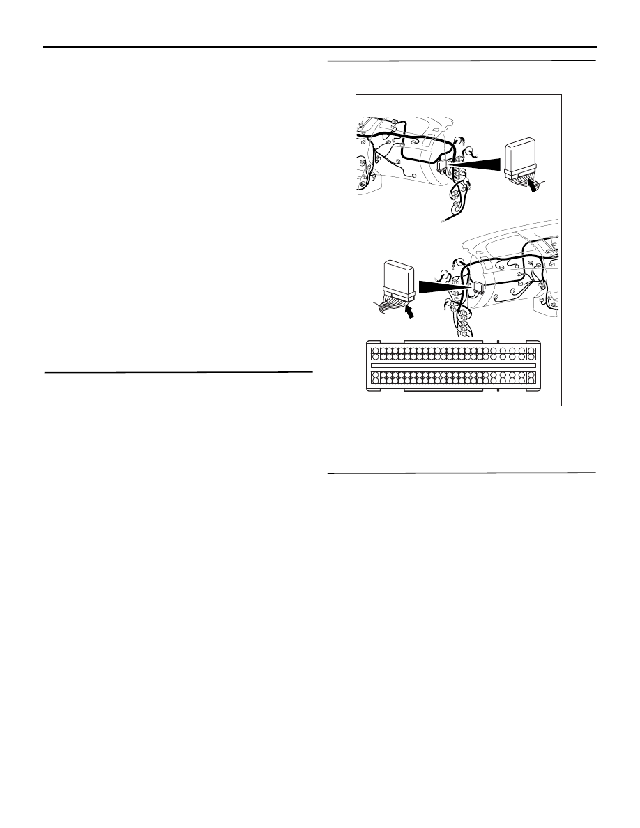
STEP 2. Connector check: C-105 engine-ECU 
connector

Q: Is the check result normal?

YES : 

Go to Step 3.

NO : 

Repair or replace.

STEP 3. Check the trouble symptoms.

Q: Does trouble symptom persist?

YES : 

Replace the engine-ECU. When the engine-

ECU is replaced, write the chassis number 
(Refer to GROUP 00 

− Precautions Before 

Service 

− How to Perform Chassis Number 

Writing ). After replacing the engine-ECU, 
register the injector identification code and 
learn fuel injection (Refer to GROUP 00 

− 

Precautions Before Service 

− What The 

Common Rail Engine Learns ). After 
registering the injector identification code, 
the vehicle equipped with the DPF carries 
out the forcible DPF regeneration. (Refer to 
GROUP 17 

− Emission Control − Diesel 

Particulate Filter (DPF) System 

− Forcible 

DPF Regeneration ).

NO : 

Intermittent malfunction (Refer to GROUP 
00 

− How to Use Troubleshooting/

Inspection Service Points 

− How to Cope 

with Intermittent Malfunction ).

AKA00089

1

2

3

4

5

6

7

8

9

10

11

12

13

14

15

16

17

18

19

20

21

22

23

24

25

26

27

28

29

30

31

32

33

34

35

36

37

38

39

40

41

42

49

50

51

52

53

54

55

56

57

58

59

60

61

62

63

64

65

66

67

68

69

70

71

72

43

44

45

46

47

48

73

74

75

76

77

78

79

80

81

82

83

84

85

86

87

88

89

90

91

92

93

94

95

96

C-105 (B)

C-105 (B)

<R.H. drive vehicles>

Harness side connector

<L.H. drive vehicles>

Connector: C-105

AB

TROUBLESHOOTING

DIESEL FUEL

13A-513

Inspection Procedure 24: Power Steering Fluid Pressure Switch System

OPERATION

• It is detected whether a load is applied on the 

power steering fluid pump by steering or not, and 
the signal is inputted to the engine-ECU. When 
the power steering fluid pressure switch "ON" sig-
nal (a large load on the power steering fluid 
pump) is inputted, the engine-ECU provides the 
idle-up control.

PROBABLE CAUSES

• Failed power steering fluid pressure switch

• Damaged harness (Open or short circuit between 

power steering fluid pressure switch and engine-
ECU)

• Damaged connector (Engine-ECU connector, 

power steering fluid pressure switch connector)

• Failed engine-ECU

DIAGNOSIS PROCEDURE

STEP 1. Connector check: A-134 power steering 
fluid pressure switch connector

Q: Is the check result normal?

AKA00105

1

101 102

103104 105 106107 108109 110 111112 113 114115

118119 120 121122 123124 125126127 128 129130

131132 133 134135 136137 138139140 141142 143

146147 148 149150 151152 153154155 156 157158

117

145

116

144

127

5

8

A-115

A-27

1

Power steering fluid 
pressure switch

ON

OFF

B-R

B-R

B-R

Engine-ECU

A-134

(MU801211)

C-103

Power steering fluid pressure switch circuit

Wire colour code
B: Black  LG: Light green  G: Green  L: Blue  W: White  Y: Yellow  SB: Sky blue  BR: Brown  O: Orange  GR: Grey
R: Red  P: Pink  V: Violet  PU: Purple  SI: Silver

AB

AK501383

1

Harness side 
connector

Connector: A-134

A-134 (B)

AB

TROUBLESHOOTING

DIESEL FUEL

13A-514

YES : 

Go to Step 2 .

NO : 

Repair or replace.

STEP 2. Perform voltage measurement at A-134 
power steering fluid pressure switch connector.

• Disconnect connector, and measure at harness 

side.

• Ignition switch: ON

• Voltage between terminal No. 1 and earth.

OK: System voltage

Q: Is the check result normal?

YES : 

Go to Step 8 .

NO : 

Go to Step 3 .

STEP 3. Perform voltage measurement at C-103 
engine-ECU connector.

• Measure engine-ECU terminal voltage.

• Ignition switch: ON

• Voltage between terminal No. 127 and earth.

OK: System voltage

Q: Is the check result normal?

YES : 

Go to Step 4 .

NO : 

Go to Step 5 .

AK501383

1

Harness side 
connector

Connector: A-134

A-134 (B)

AB

AKA00090

101

102

103

104

105

106

107

108

109

110

111

112

113

114

115

118

119

120

121

122

123

124

125

126

127

128

129

130

131

132

133

134

135

136

137

138

139

140

141

142

143

146

147

148

149

150

151

152

153

154

155

156

157

158

117

145

116

144

C-103 (B)

C-103 (B)

<R.H. drive vehicles>

Harness side connector

<L.H. drive vehicles>

Connector: C-103

AB

TROUBLESHOOTING

DIESEL FUEL

13A-515

STEP 4. Connector check: C-103 engine-ECU 
connector

Q: Is the check result normal?

YES : 

Check intermediate connectors A-27 and A-

115, and repair if necessary. If intermediate 
connector are normal, check and repair 
harness between A-134 (terminal No. 1) 
power steering fluid pressure switch 
connector and C-103 (terminal No. 127) 
engine-ECU connector.

• Check output line for open circuit.

NO : 

Repair or replace.

STEP 5. Connector check: C-103 engine-ECU 
connector 

Q: Is the check result normal?

YES : 

Go to Step 6 .

NO : 

Repair or replace the connector.

AKA00090

101

102

103

104

105

106

107

108

109

110

111

112

113

114

115

118

119

120

121

122

123

124

125

126

127

128

129

130

131

132

133

134

135

136

137

138

139

140

141

142

143

146

147

148

149

150

151

152

153

154

155

156

157

158

117

145

116

144

C-103 (B)

C-103 (B)

<R.H. drive vehicles>

Harness side connector

<L.H. drive vehicles>

Connector: C-103

AB

AK501383

1

Harness side 
connector

Connector: A-134

A-134 (B)

AB

AKA00090

101

102

103

104

105

106

107

108

109

110

111

112

113

114

115

118

119

120

121

122

123

124

125

126

127

128

129

130

131

132

133

134

135

136

137

138

139

140

141

142

143

146

147

148

149

150

151

152

153

154

155

156

157

158

117

145

116

144

C-103 (B)

C-103 (B)

<R.H. drive vehicles>

Harness side connector

<L.H. drive vehicles>

Connector: C-103

AB


Content   ..  177  178  179  180   ..