Mitsubishi L200. Manual - part 178


  Index      Mitsubishi     Mitsubishi L200 - service repair manual 2012 year


Search            


Content   ..  176  177  178  179   ..


Mitsubishi L200. Manual - part 178


TROUBLESHOOTING

DIESEL FUEL

13A-508

Inspection Procedure 22: A/C Switch System

OPERATION

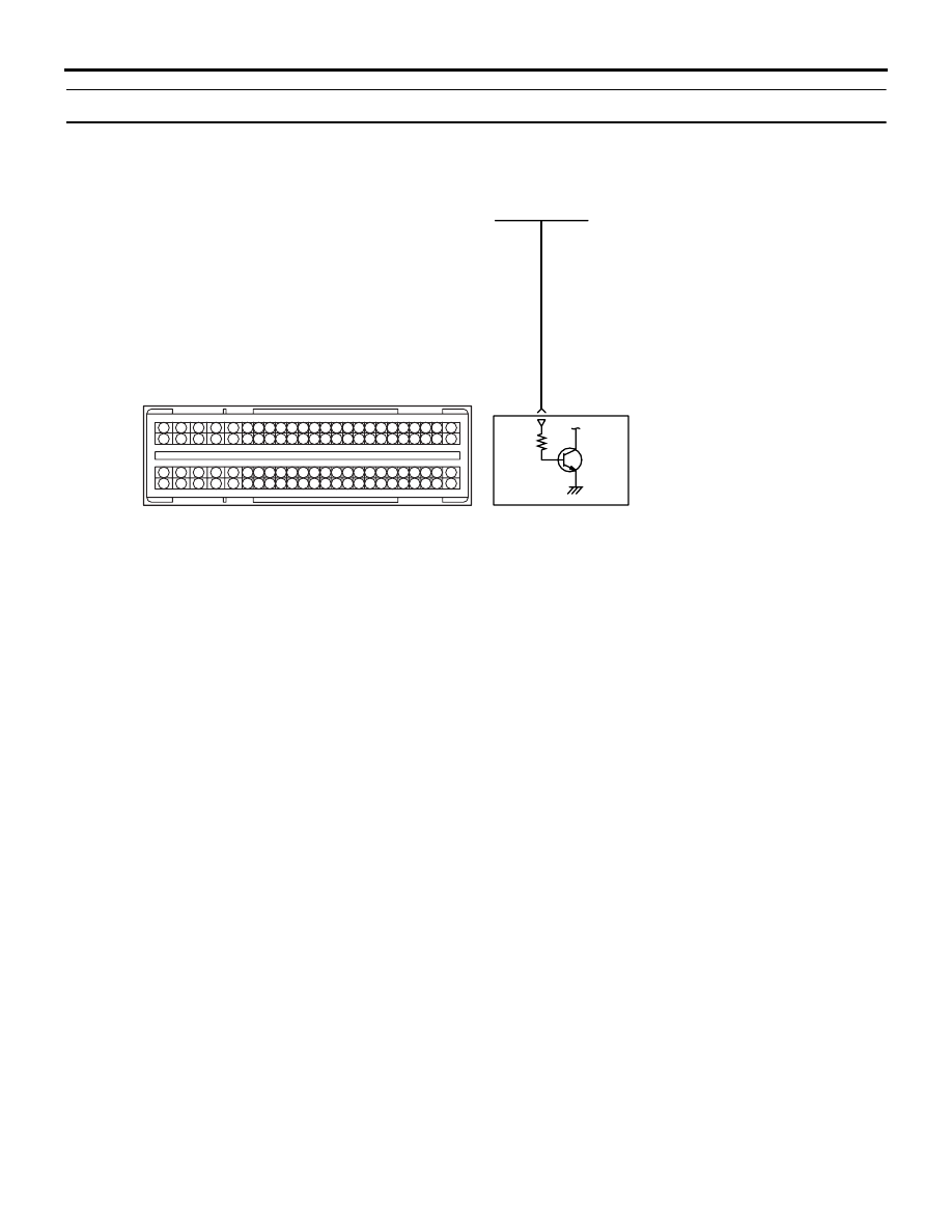
• The battery voltage is applied to the engine-ECU 

(terminal No. 8) from the A/C switch module.

PROBABLE CAUSES

• Failed A/C

• Failed A/C system

• Open/short circuit in A/C circuit or loose connec-

tor contact

• Failed engine-ECU

AKA00119

1

2

3

4

5 6 7 8 9

10 1112 13 14 15 16 17 18 19 20 21 22 23 24

25 26

27 28 29 30 31 32 33 34 35 36 37 38 39 40 41 42

49 50 51 52 53 54 55 56 57 58 59 60 61 62 63 64 65 66 67 68 69 70 71 72

43 44 45 46 47 48

73 74 75 76 77 78 79 80 81 82 83 84 85 86 87 88 89 90 91 92 93 94 95 96

BR-W

Engine-ECU

8

A/C evaporator air outlet thermistor <Manual A/C> or 

A/C-ECU <Automatic A/C>

A/C Switch circuit

C-105

Wire colour code
B: Black  LG: Light green  G: Green  L: Blue  W: White  Y: Yellow  SB: Sky blue  BR: Brown  O: Orange  GR: Grey
R: Red  P: Pink  V: Violet  PU: Purple  SI: Silver

AF

TROUBLESHOOTING

DIESEL FUEL

13A-509

DIAGNOSIS PROCEDURE

STEP 1. Perform voltage measurement at C-105 
engine-ECU connector.

• Measure engine-ECU terminal voltage.

• Engine: Idling

• A/C set temperature:

Maximum Cool when temperature in cabin is 

25

°C or more

Maximum Hot when temperature in cabin is 25

°C 

or less

• Voltage between terminal No. 8 and earth.

OK: 

System voltage (when A/C is ON)
0.5 V or less (when A/C is OFF)

Q: Is the check result normal?

YES : 

Go to Step 2 .

NO : 

 Check A/C system (Refer to GROUP 55A 

− 

Troubleshooting 

− Check Chart for Trouble 

Symptoms  <Manual A/C>, GROUP 55B 

− 

Troubleshooting 

− Check Chart for Trouble 

Symptoms  <Automatic A/C>).

STEP 2. Connector check: C-105 engine-ECU 
connector

Q: Is the check result normal?

YES : 

Go to Step 3 .

NO : 

Repair or replace.

STEP 3. M.U.T.-III data list

• Item 25: A/C switch

a. Engine: Idling
b. A/C set temperature: 

Maximum Cool when temperature in cabin is 

25

°C or more

Maximum Hot when temperature in cabin is 

25

°C or less

OK: 

ON (when A/C is ON)
OFF (when A/C is OFF)

Q: Is the check result normal?

AKA00089

1

2

3

4

5

6

7

8

9

10

11

12

13

14

15

16

17

18

19

20

21

22

23

24

25

26

27

28

29

30

31

32

33

34

35

36

37

38

39

40

41

42

49

50

51

52

53

54

55

56

57

58

59

60

61

62

63

64

65

66

67

68

69

70

71

72

43

44

45

46

47

48

73

74

75

76

77

78

79

80

81

82

83

84

85

86

87

88

89

90

91

92

93

94

95

96

C-105 (B)

C-105 (B)

<R.H. drive vehicles>

Harness side connector

<L.H. drive vehicles>

Connector: C-105

AB

TROUBLESHOOTING

DIESEL FUEL

13A-510

YES : 

Intermittent malfunction (Refer to GROUP 

00 

− How to Use Troubleshooting/

Inspection Service Points 

− How to Cope 

with Intermittent Malfunctions ).

NO : 

Replace the engine-ECU. When the engine-
ECU is replaced, write the chassis number 
(Refer to GROUP 00 

− Precautions Before 

Service 

− How to Perform Chassis Number 

Writing ). After replacing the engine-ECU, 
register the injector identification code and 
learn fuel injection (Refer to GROUP 00 

− 

Precautions Before Service 

− What The 

Common Rail Engine Learns ). After 
registering the injector identification code, 
the vehicle equipped with the DPF carries 
out the forcible DPF regeneration. (Refer to 
GROUP 17 

− Emission Control − Diesel 

Particulate Filter (DPF) System 

− Forcible 

DPF Regeneration ).

TROUBLESHOOTING

DIESEL FUEL

13A-511

Inspection Procedure 23: A/C Compressor Relay System

AKB00294

1

2

3
4

1

2

3

4

5 6 7 8 9

10 1112 13 14 15 16 17 18 19 20 21 22 23 24

25 26

27 28 29 30 31 32 33 34 35 36 37 38 39 40 41 42

49 50 51 52 53 54 55 56 57 58 59 60 61 62 63 64 65 66 67 68 69 70 71 72

43 44 45 46 47 48

73 74 75 76 77 78 79 80 81 82 83 84 85 86 87 88 89 90 91 92 93 94 95 96

1

1 2 3
4 5 6

Fusible link

W

IG2

ST

LOCK

ACC

IG1

16

7.5A

4

10A

L-R

L-R

L-R

O

Ignition switch

4

C-207

C-210

7

J/B

A/C compressor relay

Relay 
box

L-W

L-W

L-W

B-O

B-O

4

1

3

1

19

2

A-21X

A-33

MU802655

A/C compressor and clutch assembly

A/C
compressor
clutch assembly

4

A-115

A/C Compressor Relay Circuit

Wire colour code
B: Black  LG: Light green  G: Green  L: Blue  W: White  Y: Yellow  SB: Sky blue  BR: Brown  O: Orange  GR: Grey
R: Red  P: Pink  V: Violet  PU: Purple  SI: Silver

C-105

Engine-ECU

9

6

A-28

A-28

A-27

C-307

OFF

ON

R

20

4

5

AB


Content   ..  176  177  178  179   ..