Mitsubishi L200. Manual - part 110


  Index      Mitsubishi     Mitsubishi L200 - service repair manual 2012 year


Search            


Content   ..  108  109  110  111   ..


Mitsubishi L200. Manual - part 110


TROUBLESHOOTING

DIESEL FUEL

13A-236

YES : 

Go to Step 7 .

NO : 

Repair the damaged harness wire.

STEP 7. M.U.T.-III data list

• Refer to Data List Reference Table 

P.13A-542

a. Item 118: No. 2 exhaust gas temperature sensor 

(catalyst temperature)

Q: Is the check result normal?

YES : 

Intermittent malfunction (Refer to GROUP 

00 

− How to Use Troubleshooting/

Inspection Service Points 

− How to Cope 

with Intermittent Malfunctions ).

NO : 

Replace the engine-ECU. When the engine-
ECU is replaced, write the chassis number 
(Refer to GROUP 00 

− Precautions Before 

Service 

− How to Perform Chassis Number 

Writing ). After replacing the engine-ECU, 
register the injector identification code and 
learn fuel injection (Refer to GROUP 00 

− 

Precautions Before Service 

− What The 

Common Rail Engine Learns ). After 
registering the injector identification code, 
carry out the forcible DPF regeneration. 
(Refer to GROUP 17 

− Emission Control − 

Diesel Particulate Filter (DPF) System 

− 

Forcible DPF Regeneration ).

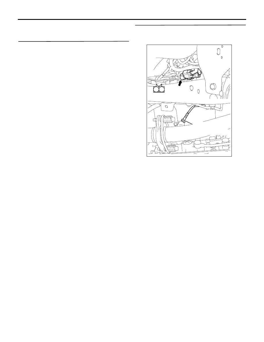
STEP 8. Perform resistance measurement at A-
159 No. 2 exhaust gas temperature sensor 
(catalyst temperature) connector.

• Disconnect connector, and measure at harness 

side.

• Resistance between terminal No. 2 and earth.

OK: Continuity (2 

 or less)

Q: Is the check result normal?

YES : 

Go to Step 11 .

NO : 

Go to Step 9 .

1

2

AKB00272

A-159 (B)

Harness side
connector

Connector: A-159

No. 2 exhaust gas
temperature sensor
(catalyst temperature)

AB

TROUBLESHOOTING

DIESEL FUEL

13A-237

STEP 9. Connector check: C-105 engine-ECU 
connector

Q: Is the check result normal?

YES : 

Go to Step 10 .

NO : 

Repair or replace the connector.

STEP 10. Check harness between A-159 (terminal 
No. 2) No. 2 exhaust gas temperature sensor 
(catalyst temperature) connector and C-105 
(terminal No. 83) engine-ECU connector.

NOTE: Before checking harness, check intemediate 
connector A-28, and repair if necessary.

• Check earthing line for open circuit and damage.

Q: Is the check result normal?

AKA00089

1

2

3

4

5

6

7

8

9

10

11

12

13

14

15

16

17

18

19

20

21

22

23

24

25

26

27

28

29

30

31

32

33

34

35

36

37

38

39

40

41

42

49

50

51

52

53

54

55

56

57

58

59

60

61

62

63

64

65

66

67

68

69

70

71

72

43

44

45

46

47

48

73

74

75

76

77

78

79

80

81

82

83

84

85

86

87

88

89

90

91

92

93

94

95

96

C-105 (B)

C-105 (B)

<R.H. drive vehicles>

Harness side connector

<L.H. drive vehicles>

Connector: C-105

AB

1

2

AKB00272

A-159 (B)

Harness side
connector

Connector: A-159

No. 2 exhaust gas
temperature sensor
(catalyst temperature)

AB

AKA00089

1

2

3

4

5

6

7

8

9

10

11

12

13

14

15

16

17

18

19

20

21

22

23

24

25

26

27

28

29

30

31

32

33

34

35

36

37

38

39

40

41

42

49

50

51

52

53

54

55

56

57

58

59

60

61

62

63

64

65

66

67

68

69

70

71

72

43

44

45

46

47

48

73

74

75

76

77

78

79

80

81

82

83

84

85

86

87

88

89

90

91

92

93

94

95

96

C-105 (B)

C-105 (B)

<R.H. drive vehicles>

Harness side connector

<L.H. drive vehicles>

Connector: C-105

AB

TROUBLESHOOTING

DIESEL FUEL

13A-238

YES : 

Go to Step 7 .

NO : 

Repair the damaged harness wire.

STEP 11. Connector check: C-105 engine-ECU 
connector.

Q: Is the check result normal?

YES : 

Go to Step 12 .

NO : 

Repair or replace the connector.

STEP 12. Check harness between A-159 (terminal 
No. 1) No. 2 exhaust gas temperature sensor 
(catalyst temperature) connector and C-105 
(terminal No. 59) engine-ECU connector.

NOTE: Before checking harness, check intemediate 
connector A-28, and repair if necessary.

• Check output line for damage.

Q: Is the check result normal?

AKA00089

1

2

3

4

5

6

7

8

9

10

11

12

13

14

15

16

17

18

19

20

21

22

23

24

25

26

27

28

29

30

31

32

33

34

35

36

37

38

39

40

41

42

49

50

51

52

53

54

55

56

57

58

59

60

61

62

63

64

65

66

67

68

69

70

71

72

43

44

45

46

47

48

73

74

75

76

77

78

79

80

81

82

83

84

85

86

87

88

89

90

91

92

93

94

95

96

C-105 (B)

C-105 (B)

<R.H. drive vehicles>

Harness side connector

<L.H. drive vehicles>

Connector: C-105

AB

1

2

AKB00272

A-159 (B)

Harness side
connector

Connector: A-159

No. 2 exhaust gas
temperature sensor
(catalyst temperature)

AB

AKA00089

1

2

3

4

5

6

7

8

9

10

11

12

13

14

15

16

17

18

19

20

21

22

23

24

25

26

27

28

29

30

31

32

33

34

35

36

37

38

39

40

41

42

49

50

51

52

53

54

55

56

57

58

59

60

61

62

63

64

65

66

67

68

69

70

71

72

43

44

45

46

47

48

73

74

75

76

77

78

79

80

81

82

83

84

85

86

87

88

89

90

91

92

93

94

95

96

C-105 (B)

C-105 (B)

<R.H. drive vehicles>

Harness side connector

<L.H. drive vehicles>

Connector: C-105

AB

TROUBLESHOOTING

DIESEL FUEL

13A-239

YES : 

Go to Step 7 .

NO : 

Repair the damaged harness wire.

Code No. P0489: EGR Valve Position Sensor Circuit Low Input <Euro5>

OPERATION

• A power voltage of 5 V is applied to the EGR 

valve assembly power terminal (terminal No. 3) 
from the engine-ECU (terminal No. 71) and 
earthed to the engine-ECU (terminal No. 81) from 
the EGR valve assembly (terminal No. 2).

• The sensor signal is inputted to the engine-ECU 

(terminal No. 57) from the EGR valve assembly 
output terminal (terminal No. 1).

FUNCTION

• The EGR valve assembly detects the position of 

the EGR valve and sends the signal to the 
engine-ECU.

• Based on the signal, the engine-ECU performs 

the feedback control of the EGR valve.

TROUBLE JUDGMENT

Check Conditions

• Battery positive voltage is 8 − 16 V

• 2 seconds later after the ignition switch has been 

in "ON" position or the engine has started up.

Judgment Criterion

• The EGR valve position sensor output voltage is 

0.20 V or less for 0.5 second.

PROBABLE CAUSES

• Failed EGR valve position sensor

• Open/short circuit or harness damage in EGR 

valve position sensor circuit or loose connector 
contact

• Failed engine-ECU

AKA00103

1

2 3

4

5 6

1

2

3

4

5 6 7 8 9

10 1112 13 14 15 16 17 18 19 20 21 22 23 24

25 26

27 28 29 30 31 32 33 34 35 36 37 38 39 40 41 42

49 50 51 52 53 54 55 56 57 58 59 60 61 62 63 64 65 66 67 68 69 70 71 72

43 44 45 46 47 48

73 74 75 76 77 78 79 80 81 82 83 84 85 86 87 88 89 90 91 92 93 94 95 96

5 V

71

3

EGR valve assembly

SB

G-B

BR-B

57

81

1

2

EGR valve Position Sensor Circuit

C-105

A-45

(MU802056)

Wire colour code
B: Black  LG: Light green  G: Green  L: Blue  W: White  Y: Yellow  SB: Sky blue  BR: Brown  O: Orange  GR: Grey
R: Red  P: Pink  V: Violet  PU: Purple  SI: Silver

Engine-ECU

AB


Content   ..  108  109  110  111   ..