Mitsubishi L200. Manual - part 111


  Index      Mitsubishi     Mitsubishi L200 - service repair manual 2012 year


Search            


Content   ..  109  110  111  112   ..


Mitsubishi L200. Manual - part 111


TROUBLESHOOTING

DIESEL FUEL

13A-240

DIAGNOSIS PROCEDURE

STEP 1. M.U.T.-III data list

• Refer to Data List Reference Table 

P.13A-542

.

a. Item 16: EGR valve position sensor

Q: Is the check result normal?

YES : 

Intermittent malfunction (Refer to GROUP 

00 

− How to Use Troubleshooting/

Inspection Service Points 

− How to Cope 

with Intermittent Malfunctions ).

NO : 

Go to Step 2 .

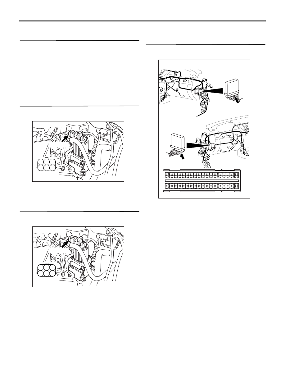
STEP 2. Connector check: A-45 EGR valve 
assembly connector

Q: Is the check result normal?

YES : 

Go to Step 3 .

NO : 

Repair or replace the connector.

STEP 3. Perform voltage measurement at A-45 
EGR valve assembly connector.

• Disconnect connector, and measure at harness 

side.

• Ignition switch: ON

• Voltage between terminal No. 3 and earth.

OK: 4.9 

 5.1 V

Q: Is the check result normal?

YES : 

Go to Step 9 . 

NO : 

Go to Step 4 

STEP 4. Perform voltage measurement at C-105 
engine-ECU connector.

• Measure engine-ECU terminal voltage.

• Ignition switch: ON

• Voltage between terminal No. 71 and earth.

OK: 4.9 

 5.1 V

Q: Is the check result normal?

YES : 

Go to Step 8 .

NO : 

Go to Step 5 .

AK501331

1

2

3

4

5

6

AB

Harness side 
connector

A-45 (GR)

Connector: A-45

AK501331

1

2

3

4

5

6

AB

Harness side 
connector

A-45 (GR)

Connector: A-45

AKA00089

1

2

3

4

5

6

7

8

9

10

11

12

13

14

15

16

17

18

19

20

21

22

23

24

25

26

27

28

29

30

31

32

33

34

35

36

37

38

39

40

41

42

49

50

51

52

53

54

55

56

57

58

59

60

61

62

63

64

65

66

67

68

69

70

71

72

43

44

45

46

47

48

73

74

75

76

77

78

79

80

81

82

83

84

85

86

87

88

89

90

91

92

93

94

95

96

C-105 (B)

C-105 (B)

<R.H. drive vehicles>

Harness side connector

<L.H. drive vehicles>

Connector: C-105

AB

TROUBLESHOOTING

DIESEL FUEL

13A-241

STEP 5. Connector check: C-105 engine-ECU 
connector

Q: Is the check result normal?

YES : 

Go to Step 6 

NO : 

Repair or replace the connector.

STEP 6. Check harness between A-45 (terminal 
No. 3) EGR valve assembly connector and C-105 
(terminal No. 71) engine-ECU connector.

• Check power supply line for short circuit.

Q: Is the check result normal?

YES : 

Go to Step 7 .

NO : 

Repair the damaged harness wire.

STEP 7. M.U.T.-III data list

• Refer to Data List Reference Table 

P.13A-542

.

a. Item 16: EGR valve position sensor

Q: Is the check result normal?

AKA00089

1

2

3

4

5

6

7

8

9

10

11

12

13

14

15

16

17

18

19

20

21

22

23

24

25

26

27

28

29

30

31

32

33

34

35

36

37

38

39

40

41

42

49

50

51

52

53

54

55

56

57

58

59

60

61

62

63

64

65

66

67

68

69

70

71

72

43

44

45

46

47

48

73

74

75

76

77

78

79

80

81

82

83

84

85

86

87

88

89

90

91

92

93

94

95

96

C-105 (B)

C-105 (B)

<R.H. drive vehicles>

Harness side connector

<L.H. drive vehicles>

Connector: C-105

AB

AK501331

1

2

3

4

5

6

AB

Harness side 
connector

A-45 (GR)

Connector: A-45

AKA00089

1

2

3

4

5

6

7

8

9

10

11

12

13

14

15

16

17

18

19

20

21

22

23

24

25

26

27

28

29

30

31

32

33

34

35

36

37

38

39

40

41

42

49

50

51

52

53

54

55

56

57

58

59

60

61

62

63

64

65

66

67

68

69

70

71

72

43

44

45

46

47

48

73

74

75

76

77

78

79

80

81

82

83

84

85

86

87

88

89

90

91

92

93

94

95

96

C-105 (B)

C-105 (B)

<R.H. drive vehicles>

Harness side connector

<L.H. drive vehicles>

Connector: C-105

AB

TROUBLESHOOTING

DIESEL FUEL

13A-242

YES : 

Intermittent malfunction (Refer to GROUP 

00 

− How to Use Troubleshooting/

Inspection Service Points 

− How to Cope 

with Intermittent Malfunctions ).

NO : 

Replace the engine-ECU. When the engine-
ECU is replaced, write the chassis number 
(Refer to GROUP 00 

− Precautions Before 

Service 

− How to Perform Chassis Number 

Writing ). After replacing the engine-ECU, 
register the injector identification code and 
learn fuel injection (Refer to GROUP 00 

− 

Precautions Before Service 

− What The 

Common Rail Engine Learns ). After 
registering the injector identification code, 
carry out the forcible DPF regeneration. 
(Refer to GROUP 17 

− Emission Control − 

Diesel Particulate Filter (DPF) System 

− 

Forcible DPF Regeneration ).

STEP 8. Connector check: C-105 engine-ECU 
connector

Q: Is the check result normal?

YES : 

Check and repair harness between A-45 

(terminal No. 3) EGR valve assembly 
connector and C-105 (terminal No. 71) 
engine-ECU connector.

• Check power supply line for open 

circuit and damage.

NO : 

Repair or replace the connector.

AKA00089

1

2

3

4

5

6

7

8

9

10

11

12

13

14

15

16

17

18

19

20

21

22

23

24

25

26

27

28

29

30

31

32

33

34

35

36

37

38

39

40

41

42

49

50

51

52

53

54

55

56

57

58

59

60

61

62

63

64

65

66

67

68

69

70

71

72

43

44

45

46

47

48

73

74

75

76

77

78

79

80

81

82

83

84

85

86

87

88

89

90

91

92

93

94

95

96

C-105 (B)

C-105 (B)

<R.H. drive vehicles>

Harness side connector

<L.H. drive vehicles>

Connector: C-105

AB

AK501331

1

2

3

4

5

6

AB

Harness side 
connector

A-45 (GR)

Connector: A-45

TROUBLESHOOTING

DIESEL FUEL

13A-243

STEP 9. Perform resistance measurement at A-45 
EGR valve assembly connector.

• Disconnect connector, and measure at harness 

side.

• Ignition switch: ON

• Resistance between terminal No. 2 and earth.

OK: Continuity (2 

 or less)

Q: Is the check result normal?

YES : 

Go to Step 12 . 

NO : 

Go to Step 10 . 

STEP 10. Connector check: C-105 engine-ECU 
connector

Q: Is the check result normal?

YES : 

Go to Step 11 .

NO : 

Repair or replace the connector.

STEP 11. Check harness between A-45 (terminal 
No. 2) EGR valve assembly connector and C-105 
(terminal No. 81) engine-ECU connector.

• Check earthing line for damage.

Q: Is the check result normal?

YES : 

Go to Step 7 .

NO : 

Repair the damaged harness wire.

AK501331

1

2

3

4

5

6

AB

Harness side 
connector

A-45 (GR)

Connector: A-45

AKA00089

1

2

3

4

5

6

7

8

9

10

11

12

13

14

15

16

17

18

19

20

21

22

23

24

25

26

27

28

29

30

31

32

33

34

35

36

37

38

39

40

41

42

49

50

51

52

53

54

55

56

57

58

59

60

61

62

63

64

65

66

67

68

69

70

71

72

43

44

45

46

47

48

73

74

75

76

77

78

79

80

81

82

83

84

85

86

87

88

89

90

91

92

93

94

95

96

C-105 (B)

C-105 (B)

<R.H. drive vehicles>

Harness side connector

<L.H. drive vehicles>

Connector: C-105

AB

AK501331

1

2

3

4

5

6

AB

Harness side 
connector

A-45 (GR)

Connector: A-45

AKA00089

1

2

3

4

5

6

7

8

9

10

11

12

13

14

15

16

17

18

19

20

21

22

23

24

25

26

27

28

29

30

31

32

33

34

35

36

37

38

39

40

41

42

49

50

51

52

53

54

55

56

57

58

59

60

61

62

63

64

65

66

67

68

69

70

71

72

43

44

45

46

47

48

73

74

75

76

77

78

79

80

81

82

83

84

85

86

87

88

89

90

91

92

93

94

95

96

C-105 (B)

C-105 (B)

<R.H. drive vehicles>

Harness side connector

<L.H. drive vehicles>

Connector: C-105

AB


Content   ..  109  110  111  112   ..