Mitsubishi L200. Manual - part 47


  Index      Mitsubishi     Mitsubishi L200 - service repair manual 2012 year


Search            


Content   ..  45  46  47  48   ..


Mitsubishi L200. Manual - part 47


CRANKSHAFT AND CYLINDER BLOCK

ENGINE OVERHAUL

11B-62

CRANKSHAFT AND CYLINDER BLOCK

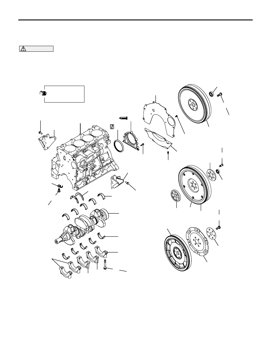
REMOVAL AND INSTALLATION

M1113008704208

CAUTION

On the flexible flywheel equipped engines, do not remove any of the bolts "A" of the flywheel shown 
in the illustration. The balance of the flexible flywheel is adjusted in an assembled condition. Remov-
ing the bolt, therefore, can cause the flexible flywheel to be out of balance giving and resulting in 
damage.

AKB00336AB

Apply engine oil to
all moving parts
before installation.

1

3

2

4

7

8

13

14

16

28

27

133 ± 4 N·m

11 ± 1 N·m

9.0 ± 1.0 N·m

133 ± 4 N·m

9.0 ± 1.0 N·m

54 ± 5 N·m

54 ± 5 N·m

40 ± 2 N·m   +35˚ to 39˚

32 ± 2 N·m

6

15

29

18

19

20

21

22

23

24

25

26

18

9

135 ± 5 N·m

12

10

A

11

5

17

Removal steps 

1.

Flywheel bolt (M/T

−2WD)

2.

Ball bearing (M/T

−2WD)

3.

Flywheel (M/T

−2WD)

4.

Flywheel bolt (M/T

−4WD)

5.

Ball bearing (M/T

−4WD)

6.

Adapter (M/T

−4WD)

7.

Flexible flywheel (M/T

−4WD)

8.

Crankshaft adapter (M/T

−4WD)

9.

Drive plate bolt (A/T)

10. Adapter plate (A/T)
11. Drive plate (A/T)
12. Inertiar  ring(A/T)
13. Rear plate
14. Bell housing cover

>>

E

<< 15. Oil seal case

>>

D

<< 16. Oil seal

>>

C

<< 17. Bearing cap bolt

>>

C

<< 18. Bearing cap

Removal steps (Continued)

CRANKSHAFT AND CYLINDER BLOCK

ENGINE OVERHAUL

11B-63

INSTALLATION SERVICE POINTS

>>A<< OIL JET INSTALLATION

AK402957

AB

Oil jet
(for No.1, 3)

Oil jet
(for No.2, 4)

No.2, 4
Cylinder

No.1, 3
Cylinder

Cylinder block

Oil jet

Knock pin

Check valve

There are two types of oil jets installed.
one for No.1 and 3 and the other for N0.2 and 4.
Make sure that the correct one is installed with cor-
rect direction as shown.

>>B<< CRANKSHAFT BEARING INSTALLATION
1. When the bearing needs replacing, select a 

proper bearing by the following procedure.
NOTE: If the crankshaft is machined to an under-
sized, bearings for undersized crankshaft should 
be used and therefore the following selection pro-
cedure is unnecessary.

AK503244

No.5
No.4
No.3
No.2
No.1

Place of journal diameter class

AB

No.5

No.4

No.3

No.2

No.1

Ident mark and color location

( Using both ID mark and color or either one )

(1) Measure the crankshaft journal diameter and 

confirm its classification from the following 
table. In the case of a crankshaft supplied as a 
service part, identification colors and marks of 
its journals and painted at the positions shown 
in the illustration.

AK402986AB

Timing belt side

No.1
No.2
No.3
No.4
No.5

(2) The cylinder block bore diameter identification 

marks are stamped at the position shown in 
the illustration from front to rear beginning at 
No.1.

AK503245AB

For upper

For lower

Identification
color

Identification mark

Identification
color

Identification mark

>>

C

<< 19. Bearing cap No.3

>>

C

<< 20. Bearing cap No.4

>>

B

<< 21. Crankshaft bearing, lower

22. Crankshaft

>>

B

<< 23. Crankshaft bearing, upper

>>

B

<< 24. Crankshaft thrust bearing

>>

A

<< 25. Check valve

>>

A

<< 26. Oil jet

27. Engine support bracket, right
28. Engine support bracket, left
29. Cylinder block

Removal steps (Continued)

CRANKSHAFT AND CYLINDER BLOCK

ENGINE OVERHAUL

11B-64

(3) Select proper bearings from the below table 

on the basis of the identification data 
confirmed under Items (1) and (2).

Example

a. If the measured value of a crankshaft journal 

outer diameter is 65.997 mm, the journal is clas-
sified as "1" or "Yellow" in the table. In case the 
crankshaft is also replaced by a spare part, check 
the identification colors of the journals painted on 
the new crankshaft.

b. Next, check the cylinder block bearing bore iden-

tification mark stamped on the cylinder block. If it 
is "A" read the "Bearing identification mark" col-
umn to find the identification mark of the bearing 
to be used. In this case, it is "1" or "Green"

Combination of crankshaft journal diameter and cylinder block bearing bore 
diameter

Bearing 
identification mark

Crankshaft journal Classification

Cylinder block bearing 
bore diameter 
identification mark

Identification color or mark
Using both ID (mark and color) or 
either one

O.D. mm

1

Yellow

65.994 

− 66.000

A

1 or Green

B

2 or Yellow

C

3 or None

2

None

65.988 

− 65.994

A

2 or Yellow

B

3 or None

C

4 or Blue

3

White

65.982 

− 65.988

A

3 or None

B

4 or Blue

C

5 or Red

AK503246AB

For upper

For lower

Groove

2. Crankshaft bearing

(1) Install the bearings having an oil groove to the 

cylinder block.

NOTE: The No. 3 bearing integrated with thrust 
bearing has no oil groove.

(2) Install the bearings having no oil groove to the 

bearing cap.

AK301467

Groove

AD

3. Crankshaft thrust bearing installation

(1) Install the two thrust bearing in the number 3 

bearing bore in the cylinder block. For easier 
installation, apply engine oil to the bearings; 
this will help hold them in position.

(2) The thrust bearings must be installed with their 

groove side toward the crankshaft web.

>>C<< BEARING CAP / BEARING CAP BOLT 
INSTALLATION

AK404143 AB

Cap No.

Front mark

CRANKSHAFT AND CYLINDER BLOCK

ENGINE OVERHAUL

11B-65

1. Install according to the front mark and cap No.
2. Apply engine oil to the threaded portion and 

seating face of the bolt.

3. Tighten the bearing cap bolts in the illustrated 

sequence to 40 

± 2 N⋅m.

AK500598AB

MB991614

CAUTION

• When the tightening angle is smaller than the 

specified tightening angle, the appropriate 
tightening capacity cannot be secured.

• When the tightening angle is larger than the 

specified tightening angle, remove the bolt to 
start from the beginning again according to 
the procedure. 

4. Using the special tool Angle gauge (MB991614), 

tighten the bearing cap bolts in the illustrated 
sequence by a further 35

° to 39°.

AK404157

5. After installing the bearing caps, make sure that 

the crankshaft turns smoothly and the end play is 
correct. If the end play exceeds the limit, replace 
crankshaft bearings.

Standard value: 0.05 

 0.25 mm

Limit: 0.45 mm

>>D<< OIL SEAL INSTALLATION

AK600423 AB

Oil seal

Oil seal case

MB992147

Press

1. Apply oil to oil seal lips.
2. Using the special tool Oil seal installer 

(MD992147), Press and fit the oil seal into the oil 
seal case to have the dimension shown in the 
illustration.

>>E<< OIL SEAL CASE INSTALLATION
1. Remove completely old FIPG remaining on the 

rear oil seal case and cylinder block.

AK500580AB

2. Apply a bead of FIPG to the surface of the rear oil 

seal case as shown in the drawing.

Specified sealant:
Three bond 1217G or equivalent

NOTE: Be sure to install the case quickly while 
the sealant is wet (within 15 minutes).

3. Install the oil seal into the cylinder block after 

applying an appropriate amount of engine oil to 
the entire circumference of its lip portion.

4. Install the rear oil seal case by tightening its bolts 

to 11 

± 1 N⋅m.

NOTE: After installation, keep the sealed area away 
from the oil for approximately one hour.


Content   ..  45  46  47  48   ..