Mitsubishi L200. Manual - part 45


  Index      Mitsubishi     Mitsubishi L200 - service repair manual 2012 year


Search            


Content   ..  43  44  45  46   ..


Mitsubishi L200. Manual - part 45


OIL PAN AND OIL PUMP

ENGINE OVERHAUL

11B-54

1. Attach the special tool Crankshaft front oil seal 

guide (MD998383) to the crankshaft and apply 
engine oil to the outer surface of the tool.

2. Using the special tool Crankshaft front oil seal 

installer (MD998382), install the front oil seal into 
the front lower case.

>>F<< FLANGE BOLT INSTALLATION

AK404132

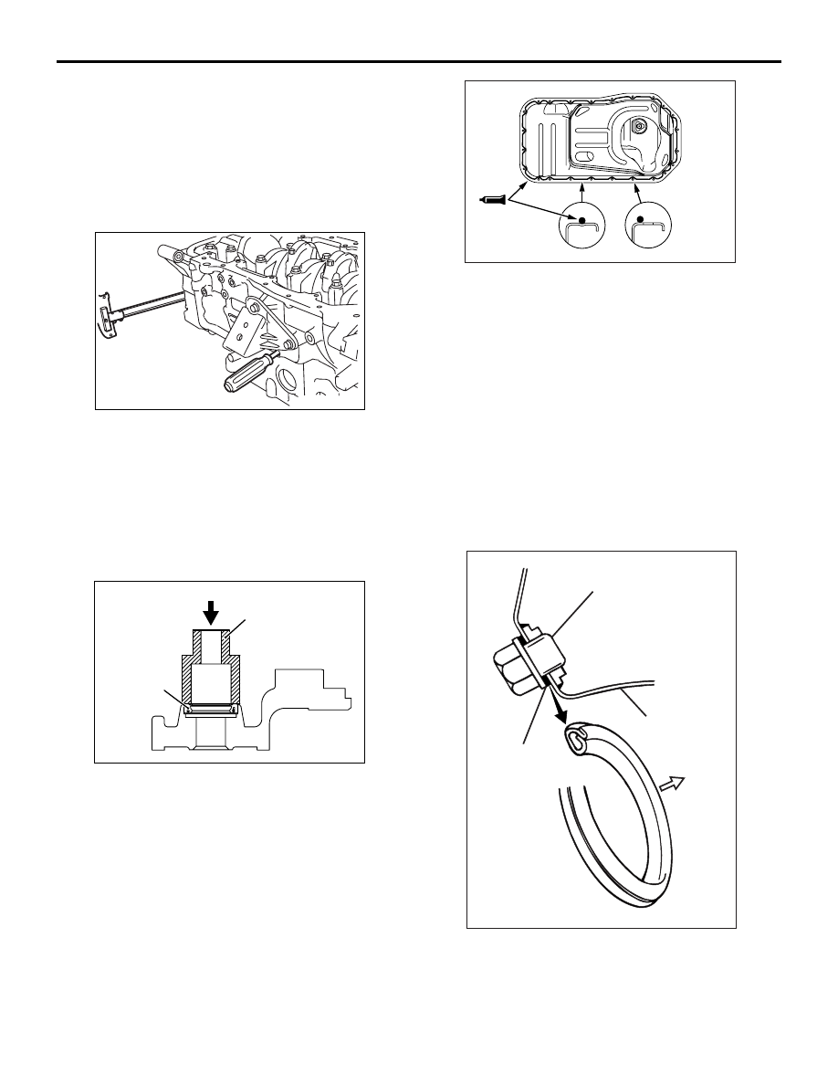
1. Insert a Phillips screwdriver into the plug hole to 

block the balancer shaft.

2. Install the flange bolt and tighten to the 

specification.

3. Remove the screwdriver and install the plug.

>>G<< FRONT UPPER CASE OIL SEAL 
INSTALLATION

AK500590AB

Socket wrench

Oil seal

Apply engine oil to the oil seal outer surface and 
drive in with a socket wrench.

>>H<< OIL PAN / OIL PAN GASKET 
INSTALLATION
Use either an oil pan gasket or a sealant for installing 
the oil pan. Install the oil pan in accordance with the 
following procedure respectively.
<SEALANT>

AK503041

Bolt 
hole 
portion

Groove 
portion

AB

1. Clean both mating surfaces of oil pan and cylinder 

block.

2. Apply a 4 mm wide bead of sealant to the entire 

circumference of the oil pan flange.

Specified sealant:
Three bond 1217G or equivalent

3. The oil pan should be installed in 15 minutes after 

the application of sealant.

<GASKET>

Clean both mating surfaces of oil pan and cylinder 
block.

>>I<< OIL DRAIN PLUG GASKET INSTALLATION

AK300601AB

Drain plug

Oil pan

Gasket

Oil pan 
side

Replace the gasket with a new one and install it in 
the direction shown in the illustration.

OIL PAN AND OIL PUMP

ENGINE OVERHAUL

11B-55

>>J<< OIL COOLER SWITCH INSTALLATION

AK404160

AB

Tab

Position the tab as shown in the illustration.

>>K<< OIL PRESSURE SWITCH INSTALLATION

AK600888

1 mm

5 mm

AB

CAUTION

Use care not to allow the sealant to plug the oil 
passage.
Apply sealant to the threads of the switch.

Specified sealant:
Three bond 1207F or equivalent

>>L<< OIL PRESSURE SWITCH INSTALLATION

AK503746 AB

CAUTION

This area shall be free from oil (antirust oil etc.) 
for switch output shall be adversely affected.

AK503747

1 mm

5 mm

AB

CAUTION

Use care not to allow the sealant to plug the oil 
passage.
1. Apply sealant to the threads of the switch.

Specified sealant:
Three bond 1207F or equivalent

AK404159

AB

MD998012

2. Using special tool Oil pressure switch socket 

wrench (MD998012), tighten the oil pressure 
switch to the specified torque.

Tightening torque: 10 

± 2 Nm

>>M<< OIL FILTER INSTALLATION

AK400405AC

Bracket 
side

1. Clean the filter mounting surface of the oil filter 

bracket.

2. Apply engine oil to the O-ring of the oil filter.

AK404129AB

General service tool

OIL PAN AND OIL PUMP

ENGINE OVERHAUL

11B-56

3. Using general service tool Oil filter wrench, Install 

the oil filter to the bracket and tighten it to the 
specified torque.

Tightening torque: 22 

± 2 Nm

4. If a torque wrench cannot be used use the 

following procedure.
(1) Screw in the oil filter until its o-ring contacts 

the oil filter bracket.

(2) Tighten the oil filter 3/4 turn.

INSPECTION

M1113008200568

FRONT LOWER CASE
1. The front case parts must be free from damage 

and cracks.

2. Install the oil pump rotor or gear into the front case 

and make sure that the rotor or gear turns 
smoothly with no excessive play in it.

3. The front case and oil pump cover surfaces in 

contact with the pump rotor or gear side face must 
be free from ridge wear.

BALANCER SHAFT

AK404141AB

Oil hole

1. Check oil holes must be free from clogging.
2. Check journal for size, damage, and contact with 

bearing. If defects are evident, replace the 
balancer shaft, bearing, or front case assembly.

3. Check the balancer shaft oil clearance. If wear is 

excessive, replace the balancer shaft bearing, 
balancer shaft or front case assembly.

Standard value

Front:

Right 0.02 

 0.05 mm

Left 0.02 

 0.06 mm

Rear: 0.06 

 0.10 mm

OIL PUMP

AK404139

1. Install the inner and outer rotors in the front case.
2. Check the tip clearance using a thickness gauge.

Standard value: 0.11 

 0.24 mm

AK404138

3. Check the side clearance using a straight edge 

and a thickness gauge.

Standard value: 0.04 

 0.10 mm

AK404140

4. Check the body clearance using a thickness 

gauge.

Standard value: 0.10 

 0.18 mm

Limit: 0.35 mm

PISTON AND CONNECTING ROD

ENGINE OVERHAUL

11B-57

PISTON AND CONNECTING ROD

REMOVAL AND INSTALLATION

M1113008403840

AK403589

1

2

3

4

5

13

6
7
8

10

11

12

14

27 ± 2 N·m   +90˚ to 94˚

Apply engine oil to
all moving parts
before installation.

9

AC

Removal steps 

>>

E

<< 1.

Connecting rod cap nut

<<

A

>> >>

E

<< 2.

Connecting rod cap

3.

Connecting rod bearing

<<

B

>> >>

D

<< 4.

Piston and connecting rod assembly

5.

Connecting rod bearing

>>

C

<< 6.

Piston ring No. 1

>>

C

<< 7.

Piston ring No. 2

>>

B

<< 8.

Oil ring

>>

A

<< 9.

Snap ring

>>

A

<< 10. Piston pin

>>

A

<< 11. Piston

>>

A

<< 12. Snap ring

13. Bolt

>>

A

<< 14. Connecting rod

Removal steps (Continued)


Content   ..  43  44  45  46   ..