Mitsubishi L200. Manual - part 37


  Index      Mitsubishi     Mitsubishi L200 - service repair manual 2012 year


Search            


Content   ..  35  36  37  38   ..


Mitsubishi L200. Manual - part 37


TIMING BELT

ENGINE OVERHAUL

11B-22

REMOVAL SERVICE POINTS

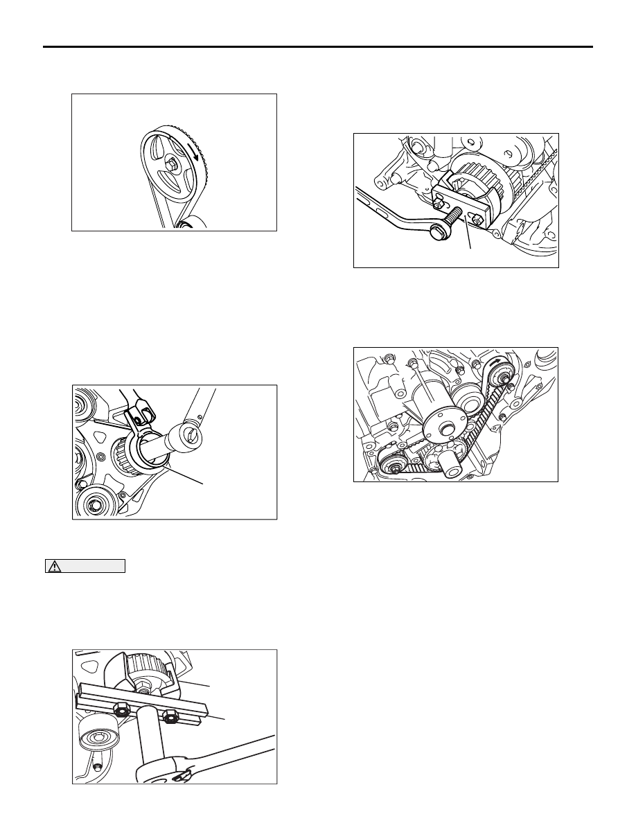
<<A>> TIMING BELT REMOVAL

AK500721

1. Using chalk, etc., mark an arrow on the back of 

the timing belt to indicate the direction of rotation. 
This is to ensure correct installation of the belt in 
case it is reused.

<<B>> AUTO TENSIONER REMOVAL
Keep the auto-tensioner longitudinal. If it were kept 
lateral, it would possibly cause aeration.

<<C>> PUMP SPROCKET REMOVAL

AK502995

MB992048

AC

1. Use the special tool Injection pump sprocket 

holder (MB992048), hold the pump sprocket.

CAUTION

Never strike the shaft or sprocket to remove the 
sprocket. This may cause malfunction in the 
injection pump. Be sure to use a puller to remove 
the sprocket.
2. Remove the pump sprocket nut.

AK503162AB

MB992098

MB992099

3. Use the special tool remove the pump sprocket.

• Injection pump sprocket puller (MB992098)

• Crank pulley puller (MB992099)

<<D>> CRANKSHAFT SPROCKET REMOVAL

AK404172 AB

MD998778

Use the special tool Crankshaft sprocket puller 
(MD998778), if the sprocket is stuck and hard to 
remove.

<<E>> TIMING BELT "B" REMOVAL

AK404168

Using chalk, etc., mark an arrow on the back of the 
timing belt to indicate the direction of rotation. This is 
to ensure correct installation of the belt in case it is 
reused.
NOTE: Water or oil on the belt shortens its life drasti-
cally, so the removed timing belt, sprocket, and ten-
sioner must be free from oil and water. Do not 
immerse parts in cleaning solvent.
NOTE: If there is oil or water on any part, check front 
case oil seals, camshaft oil seal and water pump for 
leaks.

TIMING BELT

ENGINE OVERHAUL

11B-23

<<F>> BALANCER SHAFT, RIGHT REMOVAL

AK500724

Right side

AB

Remove this 
plug and insert 
a screwdriver

1. Remove the plug at the right side of the cylinder 

block.

2. Insert a Phillips screwdriver [shank diameter 8 

mm] through the plug hole and lock the balancer 
shaft.

3. Loosen the balancer shaft sprocket nut.

<<G>> BALANCER SHAFT, LEFT REMOVAL

AK500725

Insert bar

AB

Left side

1. Insert a wrench extension bar or similar rod and 

lock the balancer shaft.

2. Loosen the balancer shaft sprocket bolt.

<<H>> CRANKSHAFT SPROCKET "B" REMOVAL

AK404167

AB

MD998778

Use the special tool Crankshaft sprocket puller 
(MD998778), if the sprocket is stuck and hard to 
remove.

INSTALLATION SERVICE POINTS

>>A<< CRANKSHAFT SPROCKET "B" INSTAL-
LATION

AK500726

Crankshaft sprocket "B"

Crankshaft

Degrease

AB

Clean and then degrease the front face of the oil 
pump gear drive shaft, crankshaft sprocket "B" and 
crankshaft surface on which sprocket "B" is attached.
NOTE: Degreasing is necessary to prevent decrease 
in the friction between contacting surfaces.

>>B<< SPACER INSTALLATION

AK402871 AB

Chamfered

Sharp edge

Spacer

Oil seal

Balancer
shaft

Install the spacer with its chamfered end toward the 
oil seal.

>>C<< BALANCER SHAFT SPROCKET, LEFT 
INSTALLATION

AK500725

Insert bar

AB

Left side

1. Lock the balancer shaft in the same way as used 

in the removal procedure.

2. Install the balancer shaft sprocket and tighten the 

bolt to the specified torque of 36 

± 3 N⋅m.

TIMING BELT

ENGINE OVERHAUL

11B-24

>>D<< BALANCER SHAFT SPROCKET, RIGHT 
INSTALLATION

AK500724

Right side

AB

Remove this 
plug and insert 
a screwdriver

1. Lock the balancer shaft in the same way as used 

in the removal procedure.

2. Install the balancer shaft sprocket and tighten the 

nut to the specified torque of 36 

± 3 N⋅m.

>>E<< TIMING BELT TENSIONER "B" 
INSTALLATION

AK500727

Washer

Front lower case

Spacer

Spring

Tensioner "B"

AB

Tensioner "B" 

Water pump

Hexagon 
socket
head bolt

Flange
bolt

1. Install the tensioner, tensioner spring and spacer.

NOTE: Be sure to install the tensioner spring with 
its shorter end toward the water pump.

2. Move tensioner "B" toward water pump and 

tighten mounting bolt.

>>F<< TIMING BELT "B" INSTALLATION

AK500728AB

Timing mark

Crankshaft
sprocket "B"

Timing mark

Timing belt "B"

1. Align timing marks on the crankshaft sprocket "B", 

and silent shaft sprockets with their timing marks.

2. Install timing belt "B" onto sprockets and ensure 

that its tension side is not slack.

AK500729

Hexagon socket
head bolt

Flange
bolt

AB

3. Loosen tensioner "B" mounting flange bolt, one to 

two turns.

4. Tighten the tensioner "B" attaching hexagon 

socket head bolt.

5. Tighten the tensioner "B" attaching flange bolt.

NOTE: If the bolt is tightened first, the tensioner 
"B" should be turned together, resulting in 
reduced timing belt "B" tension.

AK500730AB

Blancer shaft 
sprocket

Belt 
deflection

Crankshaft 
sprocket "B"

6. Ensure that the deflection is as specified when the 

belt is pushed by the index finger at the position 
indicated by an arrow.

Belt deflection: 4 

 5 mm 

TIMING BELT

ENGINE OVERHAUL

11B-25

>>G<< FLANGE / CRANKSHAFT SPROCKET 
INSTALLATION

AK500731

Crankshaft

Crankshaft
sprocket

Crankshaft 
sprocket "B"

AB

Flange

1. Clean and then degrease the following surfaces 

and parts: Sprocket mounting surface of 
crankshaft, flange, and crankshaft sprocket.
NOTE: Degreasing is necessary to prevent 
decrease in the friction between contacting sur-
faces.

2. Clean the crankshaft contacting surface of the 

crankshaft sprocket.

3. Install the flange, aligning a timing mark on a front 

lower case with that on the flange. 

>>H<< PUMP SPROCKET INSTALLATION

AK502995

MB992048

AC

1. Use the special tool Injection pump sprocket 

holder (MB992048) to prevent the pump sprocket 
from rotating.

2. Tighten the pump sprocket nut to the specified 

torque of 64 

± 5 N⋅m.

>>I<< AUTO TENSIONER INSTALLATION

CAUTION

Always bleed the auto-tensioner of air before 
installing the auto-tensioner. (Refer to auto ten-
sioner inspection 

P.11B-27

 .)

>>J<< TIMING BELT INSTALLATION

AK500734

Timing belt

Timing mark
(on pump sprocket)

AB

Timing mark
(on front 
upper case)

Timing mark
(on timing belt rear cover)

Timing mark
(on camshaft procket)

Timing mark
(on crankshaft 
sprocket "B")

Timing mark
(on front 
lower case)

1. Align the timing marks on each sprocket.
2. In accordance with the following procedure, install 

a timing belt not to be slack.

crankshaft sprocket 

→ idler pulley → pump 

sprocket 

→ idler pulley → camshaft sprocket → 

tensioner pulley


Content   ..  35  36  37  38   ..