Mazda CX-9 Grand Touring. Manual - part 423


  Index      Mazda     Mazda CX-9 Grand Touring - service repair manual 2008 year


Search            


Content   ..  421  422  423  424   ..


Mazda CX-9 Grand Touring. Manual - part 423


8. Console cover (See CONSOLE COVER REMOVAL/INSTALLATION .)  

9. Console (See CONSOLE REMOVAL/INSTALLATION .)  

4. Remove in the order indicated in the table.  

5. Install in the reverse order of removal. 

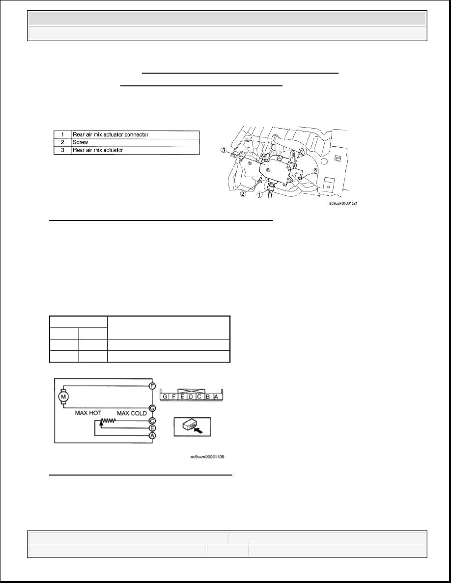
Fig. 15: Identifying Rear Air Mix Actuator Removal Order 
Courtesy of MAZDA MOTORS CORP. 

REAR AIR MIX ACTUATOR INSPECTION 

1. Connect battery positive voltage to rear air mix actuator terminal F (or G), connect terminal G (or F) to 

ground, and then verify that the rear air mix actuator operates as shown in the table. 

If the operation condition is not normal, replace the rear air mix actuator.  

REAR AIR MIX ACTUATOR OPERATION 

Fig. 16: Rear Air Mix Actuator Circuit Diagram 
Courtesy of MAZDA MOTORS CORP.

Terminal

Rear air mix actuator operation

F

G

B+

Ground

HOT --> COLD

Ground

B+

COLD --> HOT


2008 Mazda CX-9 Grand Touring 

2008 HVAC Control System (HVAC) - Mazda CX-9


Microsoft 


Sunday, November 15, 2009 10:12:35 AM

Page 10 

© 2005 Mitchell Repair Information Company, LLC. 

Fig. 17: Rear Air Mix Actuator Inspection 
Courtesy of MAZDA MOTORS CORP. 

2. Verify that the resistance between the terminals terminals C and E, and E and A matches the rear air mix 

actuator operation as shown in the graph. 

If the operation condition and resistance are not normal, replace the rear air mix actuator. 

Fig. 18: Rear Air Mix Actuator Operation Terminals C & E With E & A Resistance Graph 
Courtesy of MAZDA MOTORS CORP. 

FRONT AIRFLOW MODE ACTUATOR REMOVAL/INSTALLATION 

1. Disconnect the negative battery cable.  

2. Remove the following parts: 

1. Decoration panel (See DECORATION PANEL REMOVAL/INSTALLATION .)  

2. Front console box mat (See FRONT CONSOLE BOX MAT REMOVAL/INSTALLATION .)  

3. Indicator panel (See INDICATOR PANEL REMOVAL/INSTALLATION .)  

4. Front console box (See FRONT CONSOLE BOX REMOVAL/INSTALLATION .)  

5. Dashboard under cover (See DASHBOARD UNDER COVER REMOVAL/INSTALLATION .) 

6. Side wall (See SIDE WALL REMOVAL/INSTALLATION .)  

7. Console panel (See CONSOLE PANEL REMOVAL/INSTALLATION .)  

8. Console cover (See CONSOLE COVER REMOVAL/INSTALLATION .)  

9. Console (See CONSOLE REMOVAL/INSTALLATION .) 


2008 Mazda CX-9 Grand Touring 

2008 HVAC Control System (HVAC) - Mazda CX-9


Microsoft 


Sunday, November 15, 2009 10:12:35 AM

Page 11 

© 2005 Mitchell Repair Information Company, LLC. 

10. Front scuff plate inner (See FRONT SCUFF PLATE REMOVAL/INSTALLATION .)  

11. Front side trim (See FRONT SIDE TRIM REMOVAL/INSTALLATION .)  

12. Glove compartment (See GLOVE COMPARTMENT REMOVAL/INSTALLATION .)  

13. Hood release lever (See HOOD LATCH AND RELEASE LEVER 

REMOVAL/INSTALLATION .)  

14. Lower panel (See LOWER PANEL REMOVAL/INSTALLATION .)  

15. Lower column cover (See COLUMN COVER REMOVAL/INSTALLATION .)  

16. Driver-side air bag module (See DRIVER-SIDE AIR BAG MODULE 

REMOVAL/INSTALLATION .)  

17. Steering wheel (See STEERING WHEEL AND COLUMN REMOVAL/INSTALLATION .)  

18. Combination switch (See COMBINATION SWITCH REMOVAL/INSTALLATION .)  

19. Center panel (See CENTER PANEL REMOVAL/INSTALLATION .)  

20. Meter hood (See METER HOOD REMOVAL/INSTALLATION .)  

21. Instrument cluster (See INSTRUMENT CLUSTER REMOVAL/INSTALLATION .)  

22. Audio unit (See AUDIO UNIT REMOVAL/INSTALLATION .)  

23. Steering shaft (See STEERING WHEEL AND COLUMN REMOVAL/INSTALLATION .)  

24. A-pillar trim (See A-PILLAR TRIM REMOVAL/INSTALLATION .)  

25. Side panel (See SIDE PANEL REMOVAL/INSTALLATION .)  

3. Disconnect the front door wiring harness connector (Driver side). (See FRONT DOOR MODULE 

REMOVAL/INSTALLATION .)  

4. Disconnect the dashboard harness connectors.  

5. Remove the brake switch from the brake pedal with the brake switch connector connected. (See BRAKE 

PEDAL REMOVAL/INSTALLATION .)  

6. Remove the selector lever component. (See SELECTOR LEVER COMPONENT 

REMOVAL/INSTALLATION .)  

7. Remove the windshield wiper arm and blade. (See WINDSHIELD WIPER ARM AND BLADE 

REMOVAL/INSTALLATION .)  

8. Remove the cowl grille. (See COWL GRILLE REMOVAL/INSTALLATION .)  

9. Remove the windshield wiper motor. (See WINDSHIELD WIPER MOTOR 

REMOVAL/INSTALLATION .)  

10. Remove the dashboard. (See DASHBOARD REMOVAL/INSTALLATION .)  

11. Remove in the order indicated in the table.  

12. Install in the reverse order of removal. 


2008 Mazda CX-9 Grand Touring 

2008 HVAC Control System (HVAC) - Mazda CX-9


Microsoft 


Sunday, November 15, 2009 10:12:35 AM

Page 12 

© 2005 Mitchell Repair Information Company, LLC. 

Fig. 19: Identifying Front Airflow Mode Actuator Removal Order 
Courtesy of MAZDA MOTORS CORP. 

FRONT AIRFLOW MODE ACTUATOR INSPECTION 

1. Connect battery positive voltage to front airflow mode actuator terminal F (or G), connect terminal G (or 

F) to ground, and then verify that the front airflow mode actuator operates as shown in the table. 

If the operation condition is not normal, replace the front airflow mode actuator.  

FRONT AIRFLOW MODE ACTUATOR OPERATION 

Fig. 20: Front Airflow Mode Actuator Circuit Diagram 
Courtesy of MAZDA MOTORS CORP.

Terminal

Front airflow mode actuator operation

F

G

B+

Ground

VENT --> DEFROSTER

Ground

B+

DEFROSTER --> VENT


2008 Mazda CX-9 Grand Touring 

2008 HVAC Control System (HVAC) - Mazda CX-9


Microsoft 


Sunday, November 15, 2009 10:12:35 AM

Page 13 

© 2005 Mitchell Repair Information Company, LLC. 


Content   ..  421  422  423  424   ..