Mazda CX-9 Grand Touring. Manual - part 424
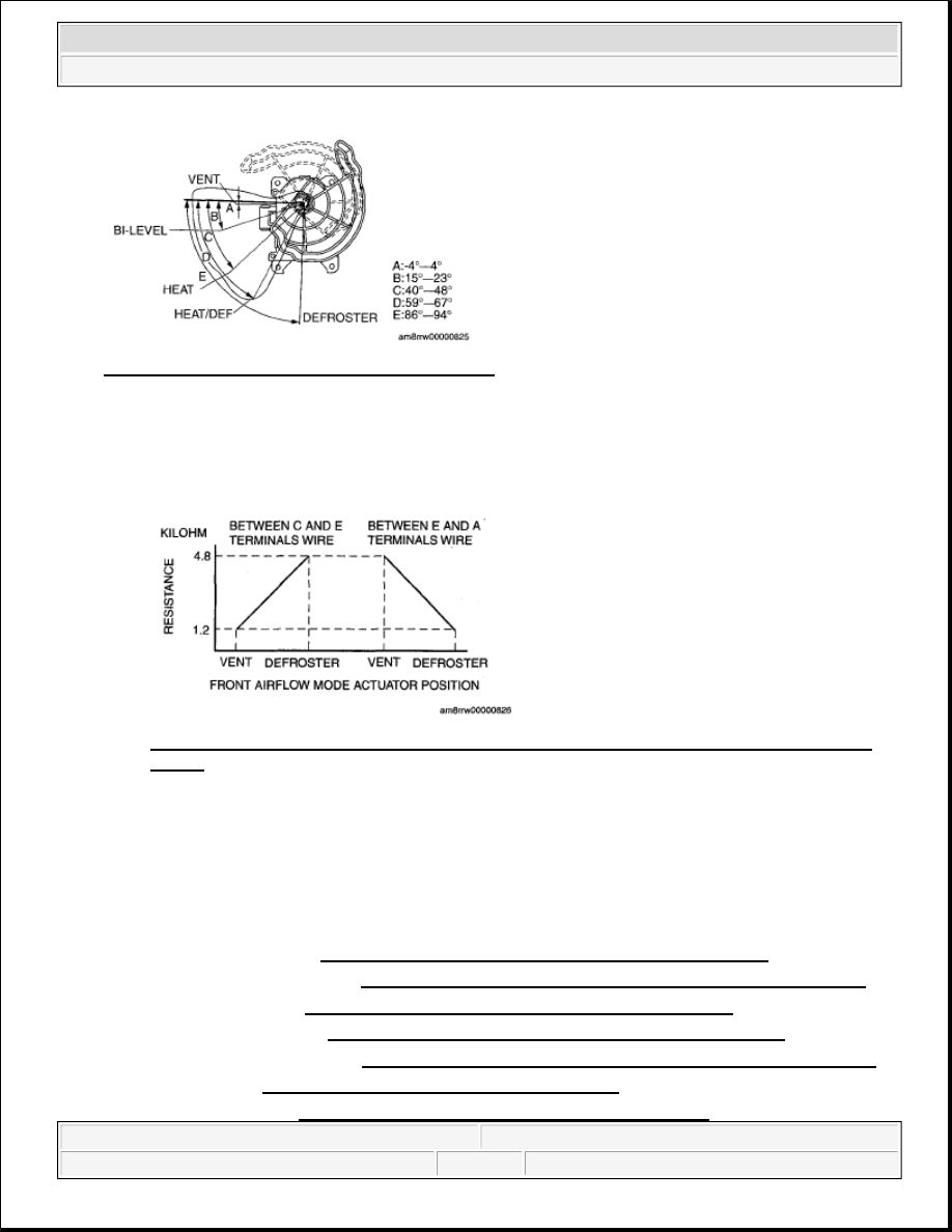
Fig. 21: Inspecting Front Airflow Mode Actuator
Courtesy of MAZDA MOTORS CORP.
2. Verify that the resistance between terminals C and E, and E and A matches the front airflow mode
actuator operation as shown in the graph.
If the operation condition and resistance are not normal, replace the front airflow mode actuator.
Fig. 22: Front Airflow Mode Actuator Operation Terminals C & E With E & A Resistance
Graph
Courtesy of MAZDA MOTORS CORP.
REAR AIRFLOW MODE ACTUATOR REMOVAL/INSTALLATION
1. Slide the passenger-side front seat to the maximum forward end.
2. Disconnect the negative battery cable.
3. Remove the following parts:
1. Decoration panel (See DECORATION PANEL REMOVAL/INSTALLATION .)
2. Front console box mat (See FRONT CONSOLE BOX MAT REMOVAL/INSTALLATION .)
3. Indicator panel (See INDICATOR PANEL REMOVAL/INSTALLATION .)
4. Front console box (See FRONT CONSOLE BOX REMOVAL/INSTALLATION .)
5. Dashboard undercover (See DASHBOARD UNDER COVER REMOVAL/INSTALLATION .)
6. Side wall (See SIDE WALL REMOVAL/INSTALLATION .)
7. Console panel (See CONSOLE PANEL REMOVAL/INSTALLATION .)
2008 Mazda CX-9 Grand Touring
2008 HVAC Control System (HVAC) - Mazda CX-9
Microsoft
Sunday, November 15, 2009 10:12:35 AM
Page 14
© 2005 Mitchell Repair Information Company, LLC.