Mazda RX7. Manual - part 10


  Index      Mazda     Mazda RX7 - service repair manual 1983 year


Search            


Content   ..  8  9  10  11   ..


Mazda RX7. Manual - part 10


ALTERNATOR & REGULATOR

Article Text (p. 3)

1983 Mazda RX7

For www.iluvmyrx7.com    

Copyright © 1998 Mitchell Repair Information Company, LLC

Sunday, August 26, 2001  03:30PM

         1) After removing through bolts, insert screwdriver between
front housing and stator to separate.
         2) Hold the rotor in a soft jawed vice. Remove pulley nut,
pulley, fan, and spacer. Remove rotor drive end housing by lightly
tapping end housing with a soft mallet.
         3) To separate stator from diode end housing, unsolder three
negative diode leads and connections between diodes. Hold the stator
lead with a needle nose plier to prevent rectifier from overheating.
         4) Remove condenser from the "B" terminal. Unsolder the "L"
and "B" terminal from the rectifier assembly. Lift out rectifier
assembly and brush holder.

         TESTING

         Diode Assemblies
         1) Check each diode with ohmmeter in forward and reverse
direction. If the diode shows large resistance in one direction and
small resistance in other direction, diode is normal.
         2) If diode shows small resistance in both directions, it is
shorted. If large resistance is shown in both directions, diode is
open. Heat sink and diodes are replaced as an assembly.

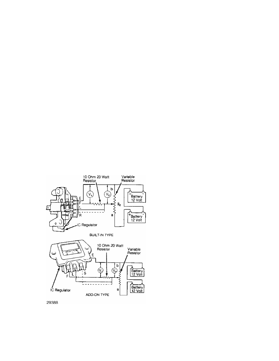
Fig. 3:  Testing Mitsubishi Integral Regulator
Ensure variable resistor is set to middle of resistance range.

         Rotor Field Continuity
         Check continuity across field coil slip rings. A reading of
3-4 ohms must be obtained. No continuity, replace rotor.

ALTERNATOR & REGULATOR

Article Text (p. 4)

1983 Mazda RX7

For www.iluvmyrx7.com    

Copyright © 1998 Mitchell Repair Information Company, LLC

Sunday, August 26, 2001  03:30PM

         Rotor Field Coil Ground
         Check continuity between individual slip rings and rotor
core/shaft. If there is continuity, coil or slip ring is grounded,
replace rotor.

         Stator Coil Ground
         Ensure no continuity exists between stator coil leads and
stator core.

         Stator Coil Continuity
         Check continuity between leads of stator coil. If there is
no continuity, replace stator.

         Brush Wear Limit
         Brushes must be replaced when worn to 1/3 of original
length. This limit is indicated by a wear limit line on the side of
each brush.

         Brush Spring Pressure
         Standard tension should be 12-16 oz. (340-453 g). Replace if
less than 7 oz. (198 g) or if springs are corroded.

         COMPONENT REPLACEMENT

         Brushes
         To remove brushes from holder, unsolder pigtail from
terminal. To replace, solder pigtail to terminal ensure that 1/4"
of brush will be located in brush holder.

         Diodes
         The diodes and rectifier are serviced as an assembly. If
any diodes are defective, replace rectifier assembly.

         Drive End Bearing
         Remove bearing retainer set screws. Press bearing out of
front housing.

         Rear Bearing
         Remove rear bearing from housing assembly using a press or
bearing puller.

         Voltage Regulator
         The voltage regulator and brush holder are combined in one
unit. If regulator is found to be defective, replace as an assembly.

         REASSEMBLY

         Reassemble by reversing disassembly procedures. Soldering of
rectifier leads should be done in less than 5 seconds to prevent
damage to diodes. When installing the rotor assembly in the rear
housing, hold the brushes in position by inserting a stiff piece of
wire into the access hole in rear housing.

ALTERNATOR & REGULATOR

Article Text (p. 5)

1983 Mazda RX7

For www.iluvmyrx7.com    

Copyright © 1998 Mitchell Repair Information Company, LLC

Sunday, August 26, 2001  03:30PM

Fig. 4:  Exploded View of Mitsubishi Alternator

END OF ARTICLE

FUSE & FLASHER LOCATIONS

Article Text

1983 Mazda RX7

For www.iluvmyrx7.com    

Copyright © 1998 Mitchell Repair Information Company, LLC

Sunday, August 26, 2001  03:30PM

ARTICLE BEGINNING

         1983 Fuse Blocks, Flashers & Relays
         MAZDA

Fig. 1:  Fuses & Flasher Locations

FUSES & FLASHER LOCATIONS

ÄÄÄÄÄÄÄÄÄÄÄÄÄÄÄÄÄÄÄÄÄÄÄÄÄÄÄÄÄÄÄÄÄÄÄÄÄÄÄÄÄÄÄÄÄÄÄÄÄÄÄÄÄÄÄÄÄÄÄÄÄÄÄÄÄÄÄÄÄÄ

Manufacturer & Models                    Component Location in Fig. 1:

Mazda
 B2000 & B2200 Pickups
  Fuse Locations  ...............................................  (7)
  Flasher Locations  ............................................  (9)
  Relay Locations
   Check & Choke  ...............................................  (4)
   Glow Plug  ...................................................  (7)
   Horn, A/C  ...................................................  (6)
   Wipers  ......................................................  (9)

 GLC Hatchback
  Fuse Locations  ...............................................  (9)
  Flasher Locations  ............................................  (9)
  Relay Locations
   Choke, A/C; Horn  ............................................  (6)
   Wipers, Others  ..............................................  (9)

 GLC Wagon
  Fuse Locations  ...............................................  (9)
  Flasher Locations  ............................................  (9)
  Relay Locations
   Check  .......................................................  (6)
   Horn  ........................................................  (5)
   Wipers  ......................................................  (9)

 RX7


Content   ..  8  9  10  11   ..