Mazda CX 7. Manual - part 413
INTERIOR TRIM
09-17–17
09-17
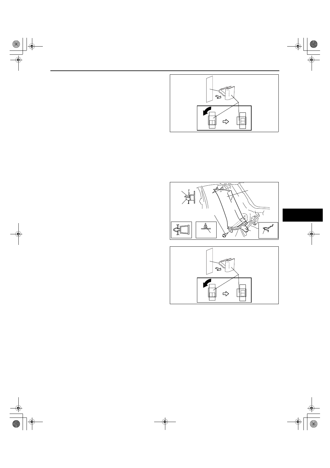
7. Turn the clip installed on the body 90
° in the
direction indicated by the arrow in the figure and
pull them out.
8. Remove clip C from the body, then install it to the
B-pillar upper trim.
9. Install in the reverse order of removal.
End Of Sie
C-PILLAR TRIM REMOVAL/INSTALLATION
id091700802200
1. Remove the following parts:
(1) Rear scuff plate inner (See 09-17-19 REAR SCUFF PLATE REMOVAL/INSTALLATION.)
(2) Rear seat (See 09-13-7 REAR SEAT REMOVAL/INSTALLATION.)
(3) Sub trunk box (See 09-17-25 SUB TRUNK BOX REMOVAL/INSTALLATION.)
(4) Trunk end trim (See 09-17-24 TRUNK END TRIM REMOVAL/INSTALLATION.)
(5) Trunk side trim (See 09-17-24 TRUNK SIDE TRIM REMOVAL/INSTALLATION.)
2. Partially peel back the seaming welt.
3. Remove the screw.
4. Pull the C-pillar trim outward and detach clip A
and pins B, C.
5. Pull the C-pillar upper trim downward and detach
the tabs and clip D.
6. Remove the C-pillar trim.
7. Turn the clip installed on the body 90
° in the
direction indicated by the arrow in the figure and
pull them out.
8. Remove clip D from the body, then install it to the
C-pillar trim.
9. Install in the reverse order of removal.
End Of Sie
CLIP C
acxuuw00002236
CLIP A
CLIP A DETAIL
PIN B
C-PILLAR TRIM
CLIP D
D
C
A
B
PIN C
SCREW
TAB
acxuuw00000681
CLIP D
acxuuw00002259