Mazda CX 7. Manual - part 342
ON-BOARD DIAGNOSTIC [BCM]
09-02F–3
09-02F
End Of Sie
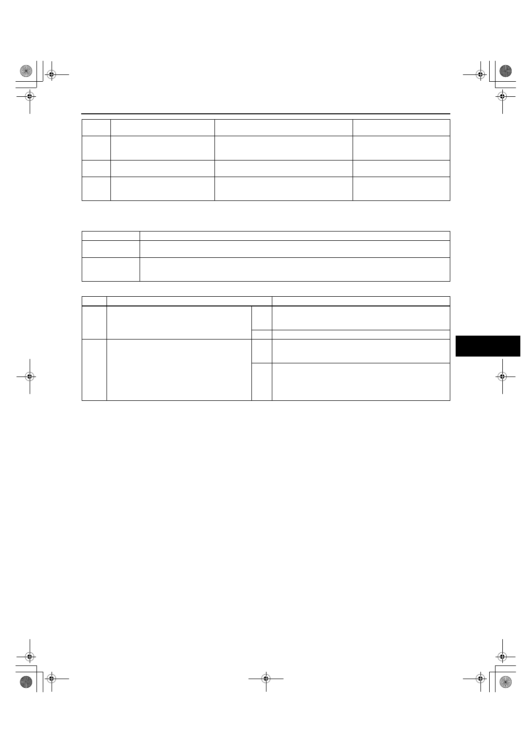
DTC B1317[BCM]
id0902f5830900
Diagnostic procedure
End Of Sie
C144A
Steering phase C circuit short to
ground
Short to GND in wiring harness between BCM
and steering angle sensor
(See 09-02F-24 DTC C1295,
C1307, C1441, C1442, C1443,
C1444, C144A, C144C[BCM].)
C1937
Steering wheel angle sensor offset
failure
BCM lost steering angle initialization position
(See 09-02F-26 DTC
C1937[BCM].)
U0073
CAN system communication error
BCM or twisted pair malfunction
(See 09-02D-14 DTC
U0073[MULTIPLEX
COMMUNICATION SYSTEM].)
DTC
No.
Description
Detection condition
Page
DTC B1317
Battery voltage high
DETECTION
CONDITION
Input voltage from the battery is excessively high
POSSIBLE
CAUSE
• Battery malfunction
• Generator malfunction
• BCM malfunction
STEP
INSPECTION
ACTION
1
INSPECT DTC FROM PCM
• Connect the M-MDS to the DLC-2.
• Are any DTCs from the PCM displayed?
Yes
Perform DTC inspection.
(See 01-02-13 DTC TABLE[L3 WITH TC].)
Go to the next step.
No
Go to the next step.
2
VERIFY TROUBLESHOOTING COMPLETED
• Make sure to reconnect all disconnected
connectors.
• Clear the DTC from the BCM memory using
the M-MDS.
• Turn the ignition switch to LOCK position
then ON position.
• Is the same DTC present?
Yes
Replace the BCM.
(See 09-40-1 BODY CONTROL MODULE (BCM)
REMOVAL/INSTALLATION.)
No
DTC troubleshooting completed.
1871-1U-06B(09-02F).fm 3 ページ 2006年3月15日 水曜日 午前11時41分