Mazda CX 7. Manual - part 343
ON-BOARD DIAGNOSTIC [BCM]
09-02F–7
09-02F
End Of Sie
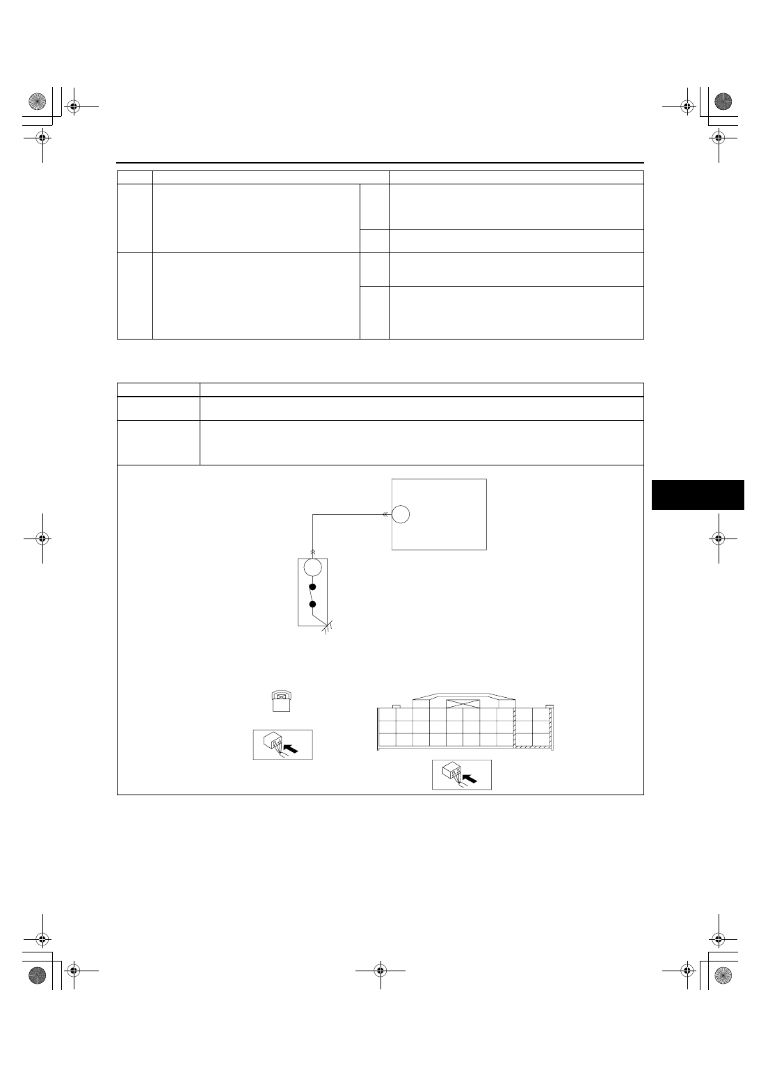
DTC B1330[BCM]
id0902f5838100
4
INSPECT FRONT DOOR LATCH AND LOCK
ACTUATOR (DRIVER-SIDE)
• Inspect the front door switch (driver-side).
(See 09-14-6 FRONT DOOR LATCH AND
LOCK ACTUATOR INSPECTION.)
• Is there any malfunction?
Yes
Replace the front door switch (driver-side), then go to the
next step.
(See 09-14-5 FRONT DOOR LATCH AND LOCK
ACTUATOR REMOVAL/INSTALLATION.)
No
Go to the next step.
5
VERIFY TROUBLESHOOTING COMPLETED
• Make sure to reconnect all disconnected
connectors.
• Clear the DTC from the BCM memory using
the M-MDS.
• Perform the self-test.
(See 09-02F-26 BCM SELF-TEST[BCM].)
• Is the same DTC present?
Yes
Replace the BCM.
(See 09-40-1 BODY CONTROL MODULE (BCM)
REMOVAL/INSTALLATION.)
No
DTC troubleshooting completed.
STEP
INSPECTION
ACTION
DTC B1330
Passenger door ajar circuit short to ground
DETECTION
CONDITION
Short to GND in wiring harness between BCM and front door switch (passenger-side)
POSSIBLE
CAUSE
• Short to GND in wiring harness between BCM terminal 5V and front door switch (passenger-side)
terminal G
• Front door switch malfunction
• BCM malfunction
5V
A
BCM
A
5Q
5K
5B
5E
5H
5AC
5N
5Z
5T
5W
5G
5D
5A
5O
5AA
5U
5X
5Y
5V
5S
5P
5M
5AD
5AB
5I
5F
5J
5C
5L
5R
FRONT DOOR SWITCH
FRONT DOOR SWITCH WIRING
HARNESS-SIDE CONNECTOR
BCM WIRING HARNESS-SIDE
CONNECTOR
1871-1U-06B(09-02F).fm 7 ページ 2006年3月15日 水曜日 午前11時41分