Mazda CX 7. Manual - part 272


  Index      Mazda     Mazda CX 7 - service repair manual 2007 year


Search            


Content   ..  270  271  272  273   ..


Mazda CX 7. Manual - part 272


POWER STEERING 

06-14–5

06-14

10. Remove the SSTs. Install and tighten the pressure pipe to the specified torque.

Tightening torque

29.4— 44.1 N·m {3.0— 4.4 kgf·m, 22— 32 ft·lbf}

11. Bleed the air from the system.

End Of Sie

WM: STEERING WHEEL AND COLUMN

STEERING WHEEL AND COLUMN INSPECTION

id061400800300

Steering Wheel Play Inspection

1. With the wheels in the straight-ahead position, gently turn the steering wheel to the left and right and verify that 

the play is within the specification.

• If the play exceeds the specification, either the steering joints are worn or the backlash of the steering gear 

is excessive. Correct as necessary.

Steering wheel play

0— 30 mm {0— 1.18 in}

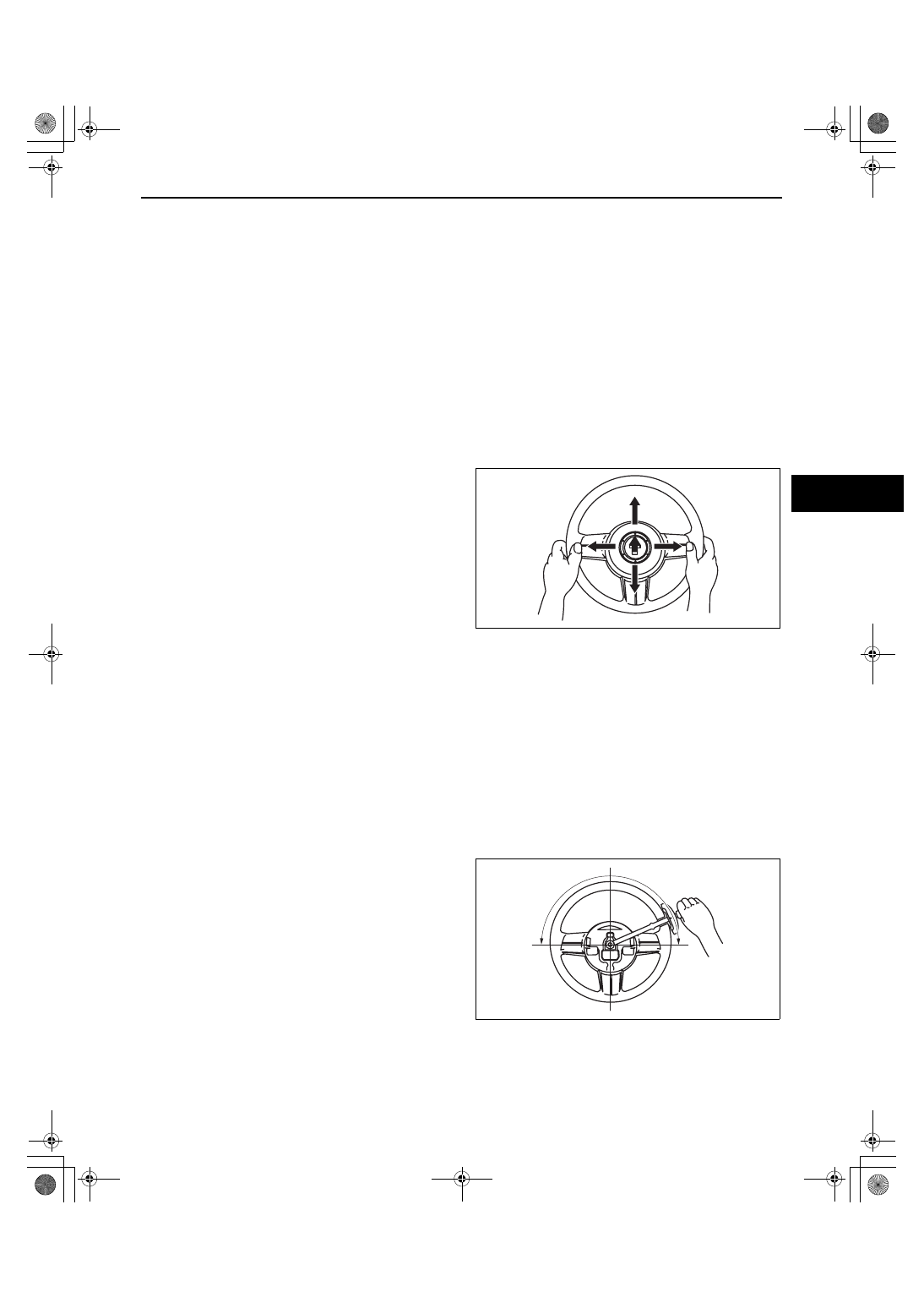
Steering Wheel Looseness Inspection

1. Move the steering wheel as shown in the figure to 

inspect for column bearing wear, steering shaft 
joint play, steering wheel looseness, and column 
looseness.

• Repair or replace as necessary.

Steering Wheel Effort Inspection

1. Inspect the following points:

• Tire size and tire pressure

• Fluid level

• Drive belt deflection

2. With the vehicle on a hard, level surface, put the wheels in the straight-ahead position.
3. Remove the air bag module.

Warning

• Handling the air bag module improperly can accidentally deploy the air bag module, which may 

seriously injure you. Read AIR BAG SYSTEM WARNINGS before handling the air bag module. (See 
08-10-3 AIR BAG SYSTEM SERVICE WARNINGS.) (See 08-10-5 AIR BAG SYSTEM SERVICE 
CAUTIONS.)

4. Start the engine and warm the power steering fluid to 50— 60 

°C {122— 140 °F}.

5. Measure the steering wheel effort using a torque 

wrench.

• If not within the specification, verify the 

following:

— No air in steering system

— No fluid leakage at hose or connectors

— Function of oil pump and steering gear

Steering wheel effort (reference value)

7.8 N·m {80 kgf·cm, 69 in·lbf} max.

Note

• To determine whether the steering effort is 

satisfactory or not, perform the inspection on 
another vehicle of the same model and under the same conditions, and compare the results.

• The steering wheel effort varies with conditions as shown below.

— Road conditions, such as dry or wet, and asphalt or concrete.

— Tire conditions, such as brand, wear, and tire pressure.

acxuuw00002353

acxuuw00002354

1871-1U-06B(06-14).fm  5 ページ  2006年3月15日 水曜日 午前11時25分

POWER STEERING 

06-14–6

End Of Sie

STEERING WHEEL AND COLUMN REMOVAL/INSTALLATION

id061400800400

Warning

• Handling the air bag module improperly can accidentally deploy the air bag module, which may 

seriously injure you. Read AIR BAG SYSTEM WARNINGS before handling the air bag module. (See 
08-10-3 AIR BAG SYSTEM SERVICE WARNINGS.) (See 08-10-5 AIR BAG SYSTEM SERVICE 
CAUTIONS.)

1. Remove in the order indicated in the table.
2. Install in the reverse order of removal.
3. If the steering lock component of a vehicle equipped with the advanced keyless system is replaced, perform the 

following procedure after installation.

• Without immobilizer system

— Steering lock unit programming (See 09-14-35 STEERING LOCK UNIT ID CODE 

REGISTRATION[ADVANCED KEYLESS SYSTEM].)

• With immobilizer system

— Immobilizer system resetting (See 09-14-11 IMMOBILIZER SYSTEM COMPONENT REPLACEMENT/

KEY ADDITION AND CLEARING[ADVANCED KEYLESS SYSTEM].) (See 09-14-20 IMMOBILIZER 
SYSTEM COMPONENT REPLACEMENT/KEY ADDITION AND CLEARING[KEYLESS ENTRY 
SYSTEM].)

.

1

2

6

7

3

4

8

5

R

10

11

12

9

39.2

49.0 

{4.0

4.9, 30

36}

15.7

22.5 

{1.7

2.2, 

11.6

16.5}

18.6

26.5 

{1.9

2.7, 

14

19}

 N·m {kgf·m, ft·lbf}

R

8.8

12.8 N·m 

{89.8

130.5 kgf·cm, 77.8

113.2 in·lbf}

13

acxuuw00000494

1

Air bag module
(See 08-10-6 DRIVER-SIDE AIR BAG MODULE 
REMOVAL/INSTALLATION.)

2

Locknut

3

Steering wheel
(See 06-14-7 Steering Wheel Removal Note.)
(See 06-14-8 Steering Wheel Installation Note.)

4

Column cover
(See 09-17-8 COLUMN COVER REMOVAL/
INSTALLATION.)

5

Combination switch
(See 09-18-13 COMBINATION SWITCH 
REMOVAL/INSTALLATION.)

6

Lower panel
(See 09-17-9 LOWER PANEL REMOVAL/
INSTALLATION.)

1871-1U-06B(06-14).fm  6 ページ  2006年3月15日 水曜日 午前11時25分

POWER STEERING 

06-14–7

06-14

Steering Wheel Removal Note

Caution

• Do not try to remove the steering wheel by hitting the shaft with a hammer. The column will 

collapse.

1. Set the vehicle in the straight-ahead position.
2. Remove the steering wheel using a suitable puller.

Steering Lock Mounting Bolts Removal Note

1. Make a groove in the heads of the steering lock 

mounting bolts using a chisel and a hammer.

2. Remove the bolts using a screwdriver.
3. Disassemble the steering lock component.

Key Cylinder (Without Advanced Keyless System) Removal Note

1. Turn the key to the ACC position.
2. Push the pin and remove the outer cylinder.

Steering Lock Mounting Bolts Installation Note

1. Assemble the steering lock component to the steering shaft.
2. Verify that the lock operates correctly.
3. Install new steering lock mounting bolts.
4. Tighten the bolts until the heads break off.

7

Joint cover

8

Steering shaft
(See 06-14-8 Steering Shaft Installation Note.)

9

Dust cover

10

Steering lock mounting bolts
(See 06-14-7 Steering Lock Mounting Bolts 
Removal Note.)
(See 06-14-7 Steering Lock Mounting Bolts 
Installation Note.)

11

Steering lock component

12

Ignition switch
(See 09-21-2 IGNITION SWITCH REMOVAL/
INSTALLATION.)

13

Key cylinder (Without advanced keyless system)
(See06-14-7 Key Cylinder (Without Advanced 
Keyless System) Removal Note.)

acxuuw00000495

PIN

acxuuw00001910

acxuuw00000496

1871-1U-06B(06-14).fm  7 ページ  2006年3月15日 水曜日 午前11時25分

POWER STEERING 

06-14–8

Steering Shaft Installation Note

Caution

• Do not apply a shock in the axial direction of the shaft.

1. Lock the tilt lever.
2. Tighten nut A.
3. Tighten nut B.
4. Tighten bolt C.

Steering Wheel Installation Note

1. Make sure the wheels in the straight-ahead position, and install the steering wheel.

End Of Sie

WM: STEERING SHAFT

STEERING SHAFT INSPECTION

id061400800600

1. Inspect the following.

(1) Column bearing for damage
(2) Steering shaft length

• Replace the steering shaft component as 

necessary.

Steering shaft length

211.6 mm {8.3 in}

2. Inspect the tilt and telescope operation. 

(1) Verify that the adjusting lever moves smoothly 

from unlock position to lock position.

(2) Verify that the steering shaft is fixed firmly 

when the adjusting lever is locked.

• Replace the steering shaft component as 

necessary.

End Of Sie

WM: STEERING GEAR AND LINKAGE

C

A

B

acxuuw00000497

E6U612ZW7013

LOCKED

UNLOCKED

ADJUSTING LEVER

B6U0612W008

1871-1U-06B(06-14).fm  8 ページ  2006年3月15日 水曜日 午前11時25分


Content   ..  270  271  272  273   ..