Mazda CX 7. Manual - part 273


  Index      Mazda     Mazda CX 7 - service repair manual 2007 year


Search            


Content   ..  271  272  273  274   ..


Mazda CX 7. Manual - part 273


POWER STEERING 

06-14–9

06-14

2007 Mazda CX-7 Workshop Manual (1871–1U–06B)

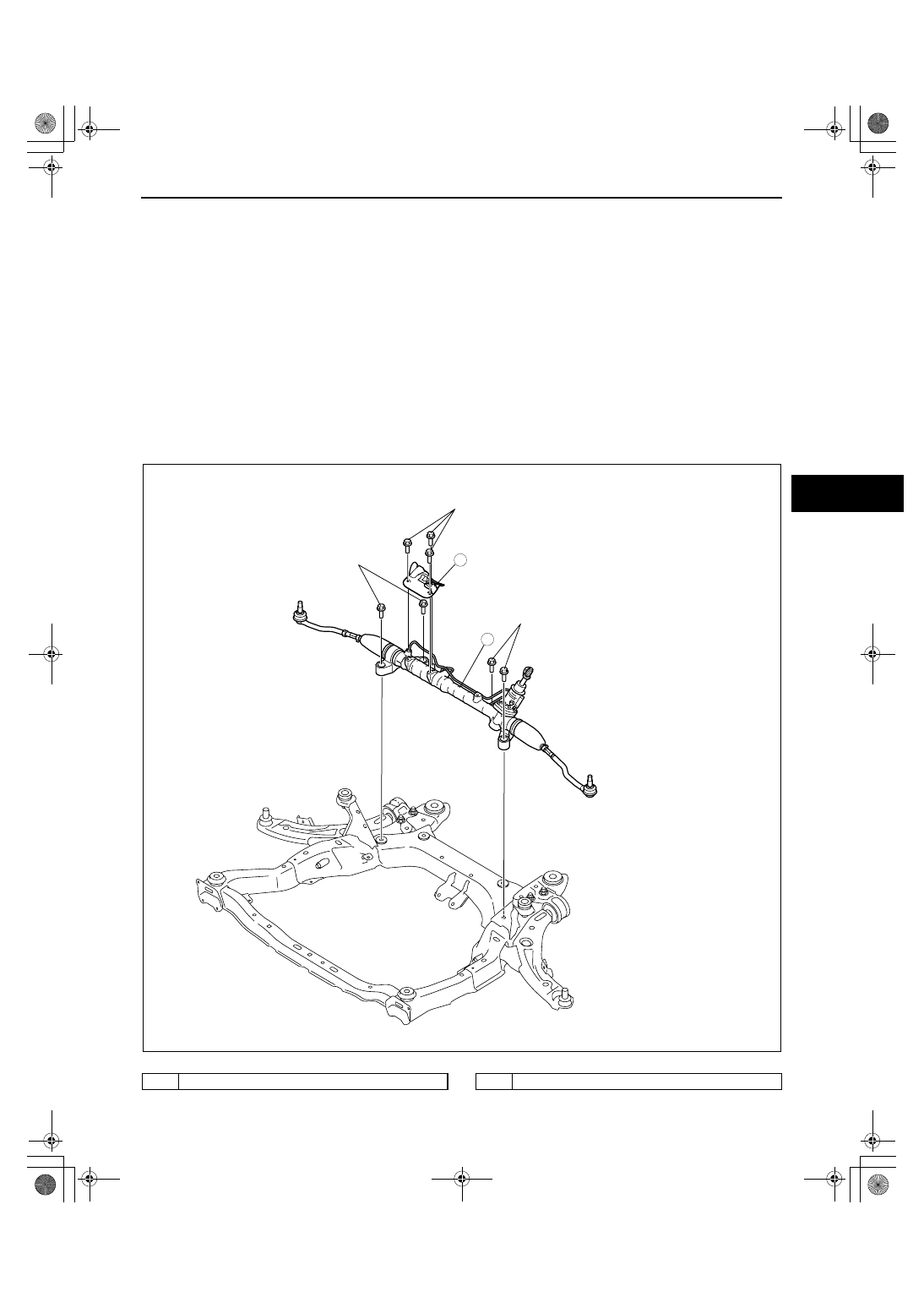
STEERING GEAR AND LINKAGE REMOVAL/INSTALLATION

id061400800900

Caution

• Performing the following procedures without first removing the ABS wheel-speed sensor may 

possibly cause an open circuit in the wiring harness if it is pulled by mistake. Before performing 
the following procedures, disconnect the ABS wheel-speed sensor connector (axle side) and fix 
the wiring harness to an appropriate place where it will not be pulled by mistake while servicing 
the vehicle.

1. Remove the transverse member. (See 02-13-14 TRANSVERSE MEMBER REMOVAL/INSTALLATION.)
2. Remove the front crossmember, lower arm, front stabilizer, and steering gear and linkage as a single unit. (See 

02-13-10 FRONT CROSSMEMBER REMOVAL/INSTALLATION.)

3. Remove the front stabilizer from the crossmember component. (See 02-13-8 FRONT STABILIZER REMOVAL/

INSTALLATION.)

4. Remove in the order indicated in the table.
5. Install in the reverse order of removal.
6. After installation, inspect the front wheel alignment and adjust it if necessary. (See 02-11-2 FRONT WHEEL 

ALIGNMENT.)

.

2

1

N·m {kgf·m, ft·lbf}

7.8—10.8 
{0.80—1.10, 
5.76— 7.96}

74.4—104.8 
{7.59— 10.6, 
54.9—77.2, }

74.4—104.8 
{7.59— 10.6, 
54.9—77.2, }

acxuuw00001950

1

Insulator

2

Steering gear and linkage

POWER STEERING 

06-14–10

2007 Mazda CX-7 Workshop Manual (1871–1U–06B)

Revised 7/2006 (Ref. No. R065/06)

End Of Sie

STEERING GEAR AND LINKAGE DISASSEMBLY

id061400801000

Caution

• Place copper plates, rag, or similar material in a vise, when securing the mounting bracket portion 

of the steering gear.

1. Disassemble in the order indicated in the table

9

8

8

14

13

12

2

10

11

6

6

29

28

22

24

26

25

27

23

7

7

5

5

4

4

3

3

15

18

16

17

21

19

20

1

SST

SST

SST

SST

SST

28

SST

28

SST

SST

acxuuw00002543

1

Oil  pipe

2

Return pipe

3

Tie-rod  End
(See 06-14-11 Tie-rod End Disassembly Note.)

4

Locknut

5

Boot clamp

6

Boot band

7

Boot

8

Tie-rod
(See 06-14-11 Tie-rod Disassembly Note.)

9

Locknut (adjusting cover)

(See 06-14-12 Locknut (Adjusting Cover), 
Adjusting Cover Disassembly Note.)

10

Adjusting cover

(See 06-14-12 Locknut (Adjusting Cover), 
Adjusting Cover Disassembly Note.)

11

Yoke spring

12

Support yoke

13

Housing cover

14

Locknut (pinion shaft side)

15

Pinion shaft and valve housing component

16

Clip

17

Dust cover

POWER STEERING 

06-14–11

06-14

2007 Mazda CX-7 Workshop Manual (1871–1U–06B)

Revised 7/2006 (Ref. No. R065/06) 

Tie-rod End Disassembly Note

1. Place alignment marks as shown in the figure for 

proper installation.

Tie-rod Disassembly Note

1. Lock the steering rack end (pinion gear side) 

against rotation with a wrench remove the tie rod 
using the SST.
Substitution SST

• 49 H032 351

Width across flats 34mm {1.3 in} (Torque 
control enabled wrench)

2. Install a wrench to the tie rod end and the flat 

surface of the steering rack as shown in the figure 
and remove the inner ball joint using the SST.

18

Pinion shaft
(See 06-14-12 Pinion Shaft, Oil seal (lower side) 
Disassembly Note.)

19

Oil seal (lower side)
(See06-14-12 Pinion Shaft, Oil seal (lower side) 
Disassembly Note .)

20

Bearing (upper side)
(See 06-14-12 Bearing (upper side), Oil seal 
(upper side) Disassembly Note.)

21

Oil seal (upper side)
(See 06-14-12 Bearing (upper side), Oil seal 
(upper side) Disassembly Note.)

22

Clip
(See 06-14-13 Clip Disassembly Note.)

23

Steering rack

24

Stopper

25

Rack bushing

26

O-ring

27

Oil seal
(See 06-14-13 Oil Seal Disassembly Note.)

28

Mounting rubber
(See 06-14-13 Mounting Rubber Disassembly 
Note.)

29

Gear housing

MARK

acxuuw00000654

49 H032 351

SUITABLE WRENCH

acxuuw00000952

49 H032 351

acxuuw00001725

POWER STEERING 

06-14–12

2007 Mazda CX-7 Workshop Manual (1871–1U–06B)

Revised 7/2006 (Ref. No. R065/06)

Locknut (Adjusting Cover), Adjusting Cover Disassembly Note

1. Install two nuts to the bolt across a flat 24 mm 

{0.94 in} and tighten them using a wrench.

2. Secure the adjusting cover with the bolt and nuts 

created in Step 1, and remove the locknut using 
the SST.

Caution

• If a tool such as a torque wrench is 

installed to the SST (49 E032 308), install 
the tool so that it is perpendicular to the 
SST as shown in the figure. If the tool is 
not installed as instructed, the SST can 
separate from the locknut easily which 
could cause damage to the locknut while 
doing the work.

3. Using the bolt/nut produced in Step 1, remove the 

adjusting cover.

Pinion Shaft, Oil seal (lower side) Disassembly Note

1. Press out the pinion shaft and oil seal (lower side) 

component.

Bearing (upper side), Oil seal (upper side) Disassembly Note

1. Press out the upper bearing and oil seal from the 

valve housing using the SSTs.
Substitution SST

• 49 G033 102

Outer diameter: 23— 24 mm {0.91— 0.94 in}

49 E032 308

49 E032 308

ACROSS FLAT 24 mm {0.94 in}

NUT

BOLT

acxuuw00002547

acxuuw00000953

49 G033 102

49 B032 301

acxuuw00001156


Content   ..  271  272  273  274   ..