Mazda CX 7. Manual - part 269


  Index      Mazda     Mazda CX 7 - service repair manual 2007 year


Search            


Content   ..  267  268  269  270   ..


Mazda CX 7. Manual - part 269


AUTOMATIC TRANSAXLE SHIFT MECHANISM 

05-18–11

05-18

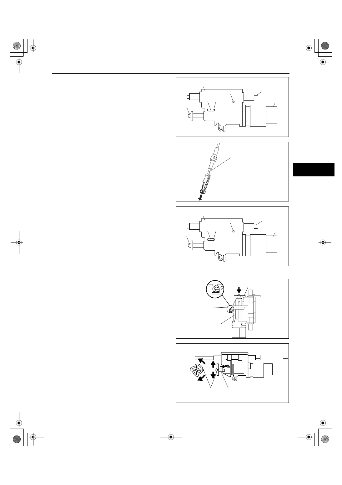
3. Push the a 1.5mm {0.059 in} round bar or similar 

into hole A by fully pushing the slider pin in.

4. Fully pull the end of the interlock cable.

5. Push the a 1.5mm {0.059 in} round bar or similar 

into hole B and hole C of the lock unit until it 
passes through.

6. Disconnect the brake switch connector.
7. Remove the brake switch. (See 04-11-6 BRAKE 

PEDAL REMOVAL/INSTALLATION.)

8. Install a new brake switch. (See 04-11-6 BRAKE 

PEDAL REMOVAL/INSTALLATION.)

Caution

• Do not connect the brake switch 

connector until the interlock cable is 
installed.

9. With the slider pin pressed, slide the lock unit to 

fix the lock unit hook into the bracket hole 
securely as shown in the figure.

Caution

• Allowing the interlock cable to be bent or 

twisted during installation can affect the 
lock unit operation.

10. Rotate the slider pin to release the lock and verify 

that it slides freely.

11. Pull the slider pin outward until it contacts the 

brake pedal stopper rubber and rotate the slider 
pin to lock.

12. Verify that the selector lever in the P position.

SLIDER PIN

INTERLOCK
CABLE

BRAKE SWITCH

A

B

C

LOCK UNIT

acxuuw00000425

INTERLOCK CABLE

acxuuw00000426

SLIDER PIN

INTERLOCK
CABLE

BRAKE SWITCH

A

B

C

LOCK UNIT

acxuuw00000425

LOCK UNIT

BRACKET

SLIDER PIN

acxuuw00000427

MARKING

SLIDER PIN

UNLOCK

LOCK

acxuuw00000428

1871-1U-06B(05-18).fm  11 ページ  2006年3月15日 水曜日 午前11時23分

AUTOMATIC TRANSAXLE SHIFT MECHANISM 

05-18–12

13. Install the interlock cable end to the cam pin on 

the selector lever.

14. Fit the interlock cable in the U–groove in the 

selector lever base plate and install the clip.

15. Press the interlock cable lock piece in until it is 

locked.

Caution

• Applying a load to the interlock cable 

while pressing the lock piece in can 
affect the lock unit operation.

16. Remove the a 1.5mm {0.059 in} round bar or 

similar from the lock unit holes A, B, and C.

17. Connect the brake switch connector with the 

brake pedal released.

Caution

• The clearance between the brake switch 

and the brake pedal is automatically 
adjusted to the correct amount when the 
brake switch connector is connected 
after the brake switch has been properly 
installed. If the brake switch is not 
properly installed or the connector is 
connected before installation, the 
clearance may be incorrect, causing a brake light malfunction. Therefore, always verify that the 
brake switch is properly installed before connecting the connector.

• Once the brake switch clearance has automatically been adjusted, it cannot be adjusted again. 

Therefore, replace the switch with a new one when replacing the power brake unit or the pedal, or 
performing any procedure that changes the pedal stroke.

18. Turn the ignition switch to ON position.
19. Install the interlock cable to the steering lock.
20. Slide the outer casing to the steering lock and 

insert the clip over the convex part of the outer 
casing.

End Of Sie

CLIP

INTERLOCK 
CABLE 

acxuuw00000429

LOCK PIECE

INTERLOCK CABLE

UNLOCK

LOCK

acxuuw00000430

SLIDER PIN

INTERLOCK
CABLE

BRAKE SWITCH

A

B

C

LOCK UNIT

acxuuw00000425

CONVEX PART

CLIP

acxuuw00001380

1871-1U-06B(05-18).fm  12 ページ  2006年3月15日 水曜日 午前11時23分

TECHNICAL DATA 

05-50–1

05-50

05-50

TECHNICAL DATA

TRANSMISSION/TRANSAXLE 

TECHNICAL DATA  . . . . . . . . . . . . . . . .  05-50–1

End of Toc

WM: TRANSMISSION/TRANSAXLE

TRANSMISSION/TRANSAXLE TECHNICAL DATA

id055000800100

Line pressure

Engine stall speed

Transaxle fluid temperature (TFT) sensor

Input/turbine speed sensor

VSS

Solenoid valve resistance (ATF temperature: 20 C {68 F})

End Of Sie

Item

Specification

Average time lag

N position 

→ D range: 1.5 s or less

N position 

→ R position: 1.5 s or less

ATF

Type: JWS3309

Capacity (Approx. quantity): 7.0 L {7.4 US qt, 6.2 lmp qt}

Distance A ((between the end of the torque converter 
and the end of the converter housing))

31.4 mm {1.24 in}

Position/range

Line pressure (kPa {kgf/cm

2

, psi})

D, M

Idle

350—410 {3.6—4.1, 51—59}

R

Idle

580—670 {6.0—6.8, 85—97}

Position/range

Engine stall speed (rpm)

D, M

2,800

R

ATF temperature (°C {°F})

Resistance (kilohm)

10 {50}

5.62—7.31

25 {77}

Approx. 3.5

110 {230}

0.22—0.27

Signal

Current (mA)

High

12.0—16.0

Low

4.0—8.0

Signal

Current (mA)

High

12.0—16.0

Low

4.0—8.0

Terminal

Solenoid valve

Resistance (ohm)

B5—GND

Shift solenoid A

11—15

B2—GND

Shift solenoid B

11—15

B11—B10

Shift solenoid C

5.0—5.6

B17—B18

Shift solenoid D

5.0—5.6

B14—B22

Shift solenoid E

5.0—5.6

B21—B16

Shift solenoid F

5.0—5.6

B9—B4

TCC control solenoid

5.0—5.6

B3—B1

Line pressure control solenoid

5.0—5.6

1871-1U-06B(05-50).fm  1 ページ  2006年3月15日 水曜日 午前11時24分


Content   ..  267  268  269  270   ..