Mazda CX 7. Manual - part 51
ON-BOARD DIAGNOSTIC [L3 WITH TC]
01-02–159
01-02
End Of Sie
DTC P0505[L3 WITH TC]
id010239808500
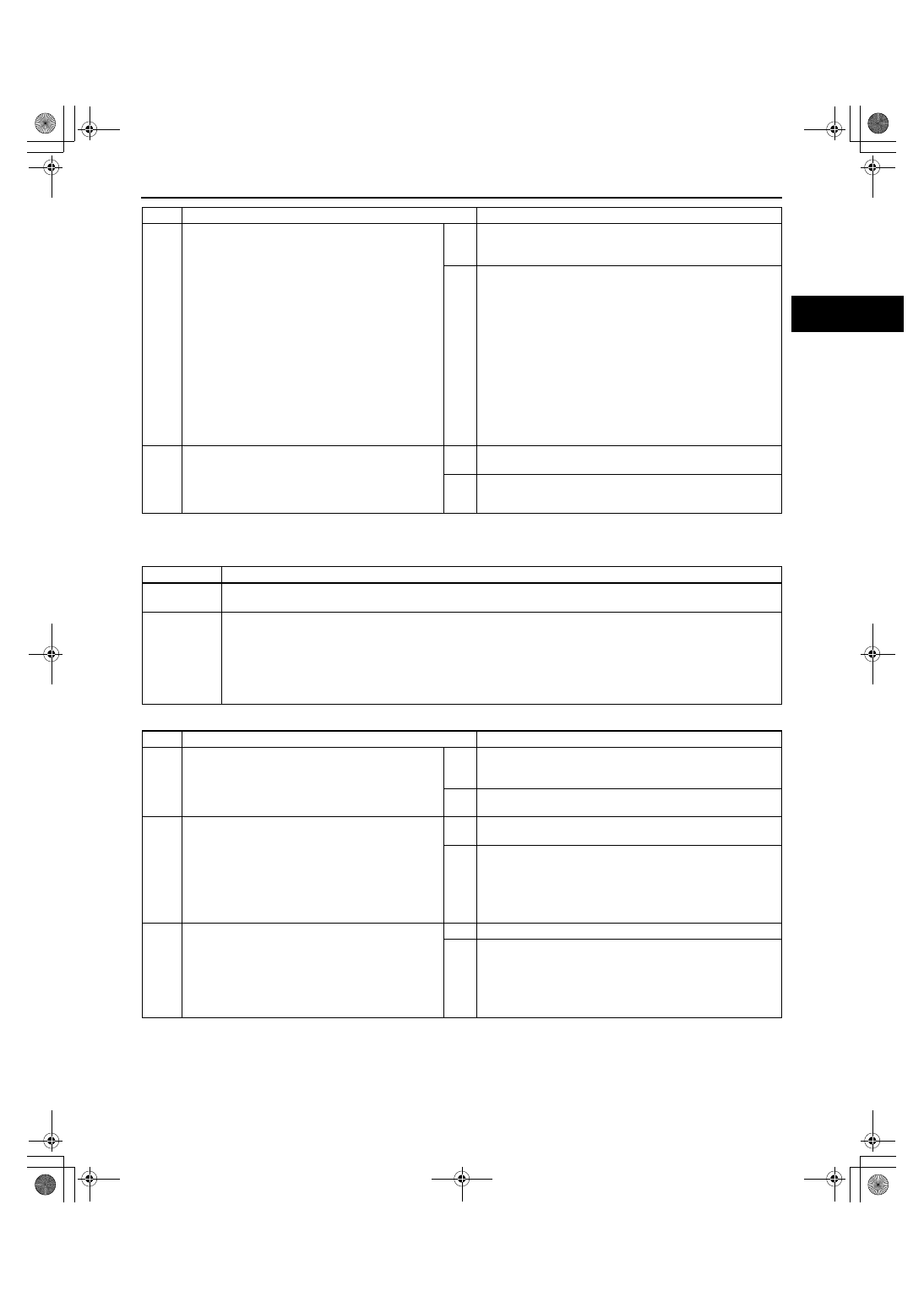
Diagnostic procedure
4
VERIFY TROUBLESHOOTING OF DTC P0500
COMPLETED
• Make sure to reconnect all disconnected
connectors.
• Turn ignition switch to the ON position (Engine
off).
• Clear the DTC from the PCM memory using
the M-MDS.
• Warm up the engine.
• Access the RPM and LOAD PID using the M-
MDS.
• Drive the vehicle under the following conditions
for 18s.
— Engine speed: 2,000 rpm or above
— Gear: Gear is in other than NEUTRAL
— Load: 40% or above
• Is the PENDING CODE for this DTC present?
Yes
Replace the PCM, then go to the next step.
(See01-40-6 PCM REMOVAL/INSTALLATION[L3 WITH
TC].)
No
Go to the next step.
5
VERIFY AFTER REPAIR PROCEDURE
• Perform the “After Repair Procedure”.
(See01-02-10 AFTER REPAIR
PROCEDURE[L3 WITH TC].)
• Are any DTCs present?
Yes
Go to the applicable DTC troubleshooting.
(See01-02-13 DTC TABLE[L3 WITH TC].)
No
Troubleshooting completed.
STEP
INSPECTION
ACTION
DTC P0505
IAC system problem
DETECTION
CONDITION
• The PCM cannot control idle speed toward the target idle speed during the KOER self test.
POSSIBLE
CAUSE
• Air cleaner element clogged
• Air intake passage clogged
• A/C relay control circuit malfunction
• Generator control circuit malfunction
• Low engine compression (Over capacity of blow-by gas)
• Electronic throttle control system improper operation
• PCM malfunction
STEP
INSPECTION
ACTION
1
VERIFY RELATED REPAIR INFORMATION
AVAILABILITY
• Check for related Service Bulletins and/or on-
line repair information availability.
• Is any related repair information available?
Yes
Perform the repair or diagnosis according to the available
repair information.
• If the vehicle is not repaired, go to the next step.
No
Go to the next step.
2
VERIFY RELATED PENDING OR STORED DTCs
• Turn the ignition switch off then to the ON
position. (Engine off)
• Verify pending code or stored DTCs using the
M-MDS.
• Are DTCs P0506, P0507, P0638, P2100,
P2101, P2102, P2103, P2108, or P2119
present?
Yes
Perform the applicable DTC troubleshooting.
(See01-02-13 DTC TABLE[L3 WITH TC].)
No
Go to the next step.
3
VERIFY ELECTRONIC THROTTLE CONTROL
SYSTEM OPERATION
• Perform the TP sweep inspection.
(See01-03-78 ENGINE CONTROL SYSTEM
OPERATION INSPECTION[L3 WITH TC].)
• Does the electronic throttle control system
work properly?
Yes
Go to the next step.
No
Repair or replace the malfunctioning part according to the
inspection result.
Then go to Step 9.
1871-1U-06B(01-02).fm 159 ページ 2006年3月15日 水曜日 午前10時32分