Mazda CX 7. Manual - part 50
ON-BOARD DIAGNOSTIC [L3 WITH TC]
01-02–155
01-02
2007 Mazda CX-7 Workshop Manual (1871–1U–06B)
End Of Sie
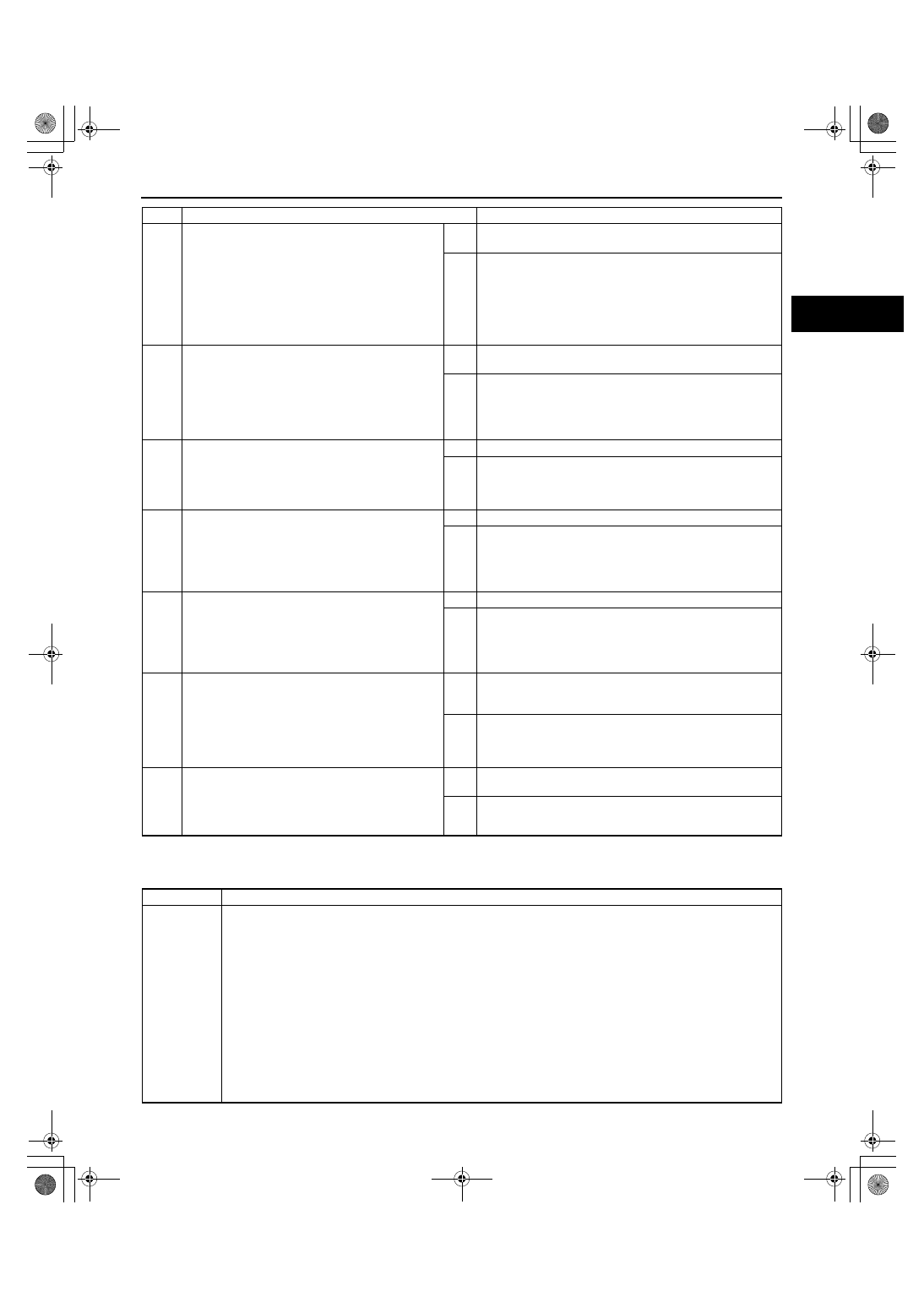
WM: DTC P05XX
DTC P050A[L3 WITH TC]
id010239800000
4
INSPECT FAN CONTROL MODULE No.2
SIGNAL CIRCUIT FOR SHORT TO POWER
SUPPLY
• Turn the ignition switch to the ON position
(Engine off).
• Measure the voltage between fan control
module No.2 terminal 2B (wiring harness-side)
and body ground.
• Is the voltage B+?
Yes
Repair or replace the wiring harness for an open circuit,
then go to Step 9.
No
Go to the next step.
5
INSPECT FAN CONTROL MODULE No.2
SIGNAL CIRCUIT FOR SHORT TO GROUND
• Turn the ignition switch off.
• Inspect for continuity between fan control
module No.2 terminal 2B (wiring harness-side)
and body ground.
• Is there continuity?
Yes
Repair or replace the wiring harness for an open circuit,
then go to Step 9.
No
Go to the next step.
6
INSPECT PCM CONNECTOR FOR POOR
CONNECTION
• Inspect for poor connection (such as damaged/
pulled-out pins, corrosion).
• Is there any malfunction?
Yes
Repair or replace the terminal, then go to Step 9.
No
Go to the next step.
7
INSPECT FAN CONTROL MODULE No.2
SIGNAL CIRCUIT FOR OPEN CIRCUIT
• Inspect for continuity between fan control
module No.2 terminal 2B (wiring harness-side)
and PCM terminal 1R.
• Is there continuity?
Yes
Go to the next step.
No
Repair or replace the wiring harness for an open circuit,
then go to Step 9.
8
INSPECT FAN CONTROL MODULE No.2
• Perform the fan control module No.2
inspection.
(See01-03-78 ENGINE CONTROL SYSTEM
OPERATION INSPECTION[L3 WITH TC].)
• Is the fan control module No.2 normal?
Yes
Go to the next step.
No
Replace the fan control module No.2, then go to the next
step.
9
VERIFY TROUBLESHOOTING OF DTC P0481
COMPLETED
• Clear the DTC from the PCM memory using
the M-MDS.
• Start the engine.
• Turn A/C switch to ON.
• Is the same DTC present?
Yes
Replace the PCM, then go to the next step.
(See01-40-6 PCM REMOVAL/INSTALLATION[L3 WITH
TC].)
No
Go to the next step.
10
VERIFY AFTER REPAIR PROCEDURE
• Perform the “AFTER REPAIR PROCEDURE”.
(See01-02-10 AFTER REPAIR
PROCEDURE[L3 WITH TC].)
• Are any DTCs present?
Yes
Go to the applicable DTC inspection.
(See01-02-13 DTC TABLE[L3 WITH TC].)
No
Troubleshooting completed.
STEP
INSPECTION
ACTION
DTC P050A
Cold start idle air control system performance
DETECTION
CONDITION
• Actual idle speed is lower than expected by 100 rpm for 8.4 s when target idle speed is above 0 rpm at
cold start or ignition retard value is above 8.9 deg.CA.
Note
• If atmospheric pressure is less than 72.3 kPa {542 mmHg, 21.3 inHg} or intake air temperature is
below -10
°C {14 °F}, the PCM cancels diagnosis of P0506.
Diagnostic support note
• This is a continuous monitor (CCM).
• The MIL illuminates if the PCM detects the above malfunction condition in two consecutive drive cycles or
in one drive cycle while the DTC for the same malfunction has been stored in the PCM.
• PENDING CODE is available if the PCM detects the above malfunction condition during the first drive
cycle.
• FREEZE FRAME DATA is available.
• DTC is stored in the PCM memory.