Mazda CX 7. Manual - part 49
ON-BOARD DIAGNOSTIC [L3 WITH TC]
01-02–151
01-02
DTC P0463[L3 WITH TC]
id010239808200
Diagnostic procedure
End Of Sie
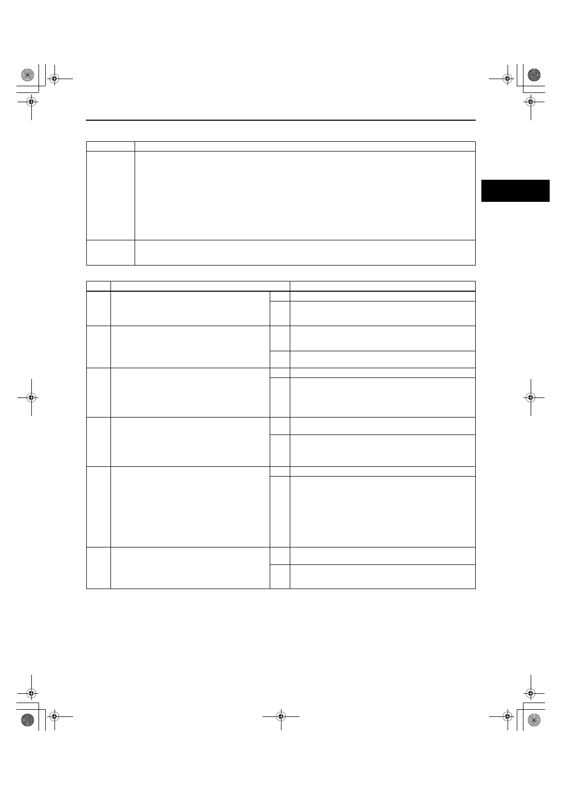
DTC P0463
Fuel gauge sender unit circuit high input
DETECTION
CONDITION
• The PCM monitors the signals of the fuel level and fuel gauge sender unit output voltage from the
instrument cluster. If the PCM detects that the fuel level or fuel gauge sender unit output voltage is too high,
the PCM determines that the fuel gauge sender unit circuit has a malfunction.
Diagnostic support note
• This is a continuous monitor (CCM).
• MIL illuminates if the PCM detects the above malfunction condition in two consecutive drive cycles or in
one drive cycle while the DTC for the same malfunction has been stored in the PCM.
• PENDING CODE is available if the PCM detects the above malfunction condition during the first drive
cycle.
• FREEZE FRAME DATA is available.
• DTCs are stored in the PCM memory.
POSSIBLE
CAUSE
• Instrument cluster malfunction
• Fuel gauge sender unit malfunction
• PCM malfunction
STEP
INSPECTION
ACTION
1
VERIFY FREEZE FRAME DATA HAS BEEN
RECORDED
• Has the FREEZE FRAME DATA been
recorded?
Yes
Go to the next step.
No
Record FREEZE FRAME DATA on the repair order, then go
to the next step.
2
VERIFY RELATED REPAIR INFORMATION
AVAILABILITY
• Check for related Service Bulletins and/or on-
line repair information availability.
• Is any related repair information available?
Yes
Perform the repair or diagnosis according to the available
repair information.
• If the vehicle is not repaired, go to the next step.
No
Go to the next step.
3
INSPECT FUEL GAUGE SENDER UNIT
• Turn the ignition switch off.
• Inspect the fuel gauge sender unit.
(See09-22-14 FUEL GAUGE SENDER UNIT
INSPECTION.)
• Is the fuel gauge sender unit normal?
Yes
Replace the PCM, then go to the next step.
No
Repair or replace the fuel gauge sender unit, then go to the
next step.
4
INSPECT INSTRUMENT CLUSTER
• Perform “INSTRUMENT CLUSTER INPUT/
OUTPUT CHECK MODE” procedure.
(See 09-22-5 INSTRUMENT CLUSTER
INPUT/OUTPUT CHECK MODE.)
• Is there any malfunction?
Yes
Repair or replace the suspected malfunction, then go to the
next step.
No
Go to the next step.
5
VERIFY TROUBLESHOOTING OF DTC P0463
COMPLETED
• Make sure to reconnect all disconnected
connectors.
• Turn ignition switch to the ON position (Engine
off).
• Clear the DTC from the memory using the M-
MDS.
• Start the engine.
• Is the PENDING CODE for this DTC present?
Yes
Replace the PCM, then go to the next step.
No
Go to the next step.
6
VERIFY AFTER REPAIR PROCEDURE
• Perform the “After Repair Procedure”.
(See 01-02-10 AFTER REPAIR
PROCEDURE[L3 WITH TC].)
• Are any DTCs present?
Yes
Go to the applicable DTC inspection.
(See 01-02-13 DTC TABLE[L3 WITH TC].)
No
Troubleshooting completed.
1871-1U-06B(01-02).fm 151 ページ 2006年3月15日 水曜日 午前10時32分