Mazda CX 7. Manual - part 41
ON-BOARD DIAGNOSTIC [L3 WITH TC]
01-02–119
01-02
End Of Sie
DTC P0301, P0302, P0303, P0304[L3 WITH TC]
id010239806600
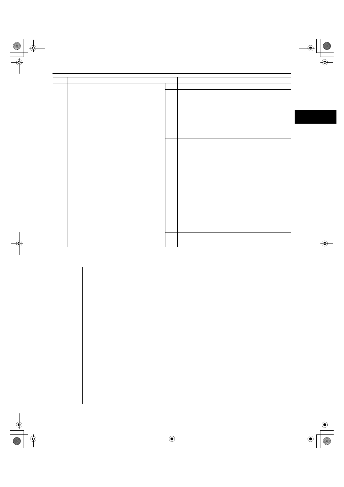
24
INSPECT FUEL PRESSURE (LOW-SIDE)
• Connect the fuel pressure gauge between the
fuel pump and the high pressure fuel pump.
• Measure the low side fuel pressure.
(See01-14-5 FUEL LINE PRESSURE
INSPECTION[L3 WITH TC].)
• Is the low side fuel pressure within the
specification?
Yes
Go to the next step.
No
Inspect for the following.
• Fuel line restriction
• Fuel filter clogging
If normal replace the fuel pump.Then go to Step 26.
25
INSPECT SEALING OF ENGINE COOLANT
PASSAGE
• Perform “ENGINE COOLANT LEAKAGE
INSPECTION.”
(See01-12-6 ENGINE COOLANT LEAKAGE
INSPECTION[L3 WITH TC].)
• Is there any malfunction?
Yes
Repair or replace the malfunctioning part according to the
inspection results.
Then go to the next step.
No
Go to the next step.
26
VERIFY TROUBLESHOOTING OF MISFIRE DTC
COMPLETED
• Make sure to reconnect all disconnected
connectors.
• Turn the ignition switch to the ON position
(Engine off).
• Clear the DTC from the memory using the M-
MDS.
• Perform the HO2S heater, HO2S, and TWC
Repair Verification Drive Mode.
(See01-02-10 OBD-II DRIVE MODE[L3 WITH
TC].)
• Is the PENDING CODE for this DTC present?
Yes
Replace the PCM, then go to the next step.
(See01-40-6 PCM REMOVAL/INSTALLATION[L3 WITH
TC].)
No
Go to the next step.
27
VERIFY AFTER REPAIR PROCEDURE
• Perform the “AFTER REPAIR PROCEDURE”.
(See01-02-10 AFTER REPAIR
PROCEDURE[L3 WITH TC].)
• Are any DTCs present?
Yes
Go to the applicable DTC troubleshooting.
(See01-02-13 DTC TABLE[L3 WITH TC].)
No
Troubleshooting completed.
STEP
INSPECTION
ACTION
DTC P0301
DTC P0302
DTC P0303
DTC P0304
Cylinder No.1 misfire detected
Cylinder No.2 misfire detected
Cylinder No.3 misfire detected
Cylinder No.4 misfire detected
DETECTION
CONDITION
• The PCM monitors the CKP sensor input signal interval time. The PCM calculates the change of interval
time for each cylinder. If the change of interval time exceeds the preprogrammed criteria, the PCM detects
a misfire in the corresponding cylinder. While the engine is running, the PCM counts the number of misfires
that occurred at 200 crankshaft revolutions and 1,000 crankshaft revolutions and calculates a misfire
ratio for each crankshaft revolution. If the ratio exceeds the preprogrammed criteria, the PCM determines
that a misfire, which can damage the catalytic converter or affect emission performance, has occurred.
Diagnostic support note
• This is a continuous monitor (Misfire).
• The MIL illuminates if the PCM detects a misfire which affects emission performance in two consecutive
drive cycles or in one drive cycle while the DTC for the same malfunction has been stored in the PCM.
• The MIL flashes if the PCM detects a misfire which can damage the catalytic converter during the first drive
cycle.
• PENDING CODE is available if the PCM detects a misfire which affects emission performance during first
drive cycle.
• FREEZE FRAME DATA is available.
• DTCs are stored in the PCM memory.
POSSIBLE
CAUSE
• Spark plug malfunction
• Ignition coil malfunction
• Ignition system malfunction
• Fuel injector malfunction
• Air suction in intake air system (between dynamic chamber and cylinder head)
• Inadequate engine compression due to engine internal malfunction
• Related connector or terminal malfunction
• Related wiring harness
1871-1U-06B(01-02).fm 119 ページ 2006年3月15日 水曜日 午前10時32分