Mazda CX 7. Manual - part 39
ON-BOARD DIAGNOSTIC [L3 WITH TC]
01-02–111
01-02
DTC P0234[L3 WITH TC]
id010239806200
Diagnostic procedure
End Of Sie
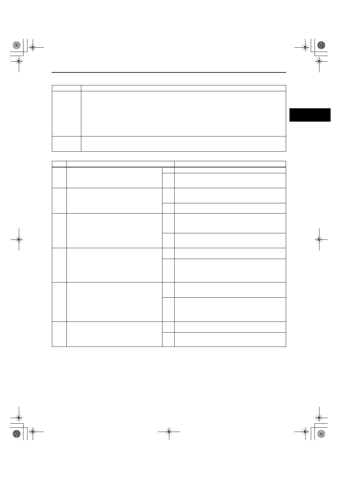
DTC P0234
Turbocharger over boost condition
DETECTION
CONDITION
• If the manifold absolute pressure or charging efficiency are more than the specification for the specified
period of time, the PCM determines that the turbocharger is in an over boost condition.
MONITORING CONDITIONS
— Engine speed is 2,000 rpm or more.
Diagnostic support note
• This is a continuous monitor (Other).
• The MIL does not illuminate.
• FREEZE FRAME DATA is not available.
• DTCs are stored in the PCM memory.
POSSIBLE
CAUSE
• Wastegate control solenoid valve malfunction
• Vacuum hose looseness or damage
• Improper installation of the vacuum hose
STEP
INSPECTION
ACTION
1
VERIFY FREEZE FRAME DATA HAS BEEN
RECORDED
• Has the FREEZE FRAME DATA been
recorded?
Yes
Go to the next step.
No
Record the FREEZE FRAME DATA on the repair order,
then go to the next step.
2
VERIFY RELATED REPAIR INFORMATION
AVAILABILITY
• Verify related Service Bulletins and/or on-line
repair information availability.
• Is any related repair information available?
Yes
Perform repair or diagnosis according to the available
repair information.
• If the vehicle is not repaired, go to the next step.
No
Go to the next step.
3
INSPECT WASTEGATE CONTROL SOLENOID
VALVE
• Inspect the wastegate control solenoid valve.
(See01-13-14 WASTEGATE CONTROL
SOLENOID VALVE INSPECTION[L3 WITH
TC].)
• Is there any malfunction?
Yes
Replace the wastegate control solenoid valve, then go to
Step 5.
(See01-13-5 INTAKE AIR SYSTEM REMOVAL/
INSTALLATION[L3 WITH TC].)
No
Go to the next step.
4
INSPECT VACUUM HOSE
• Inspect the vacuum hose condition for the
following:
— Looseness
— Damage
— Improper installation
• Is there any malfunction?
Yes
Repair or replace the suspected part, then go to the next
step.
No
Go to the next step.
5
VERIFY TROUBLESHOOTING OF DTC P0234
COMPLETED
• Make sure to reconnect all the disconnected
connectors.
• Clear the DTC from the PCM memory using
the M-MDS.
• Start the engine.
• Is the same DTC present?
Yes
Replace the PCM, then go to the next step.
(See01-40-6 PCM REMOVAL/INSTALLATION[L3 WITH
TC].)
No
Go to the next step.
6
VERIFY AFTER REPAIR PROCEDURE
• Perform the “AFTER REPAIR PROCEDURE”.
(See01-02-10 AFTER REPAIR
PROCEDURE[L3 WITH TC].)
• Are any DTCs present?
Yes
Go to the applicable DTC troubleshooting.
(See01-02-13 DTC TABLE[L3 WITH TC].)
No
DTC troubleshooting completed.
1871-1U-06B(01-02).fm 111 ページ 2006年3月15日 水曜日 午前10時32分