Mazda Protege 5. Manual - part 222
ON-BOARD DIAGNOSTIC
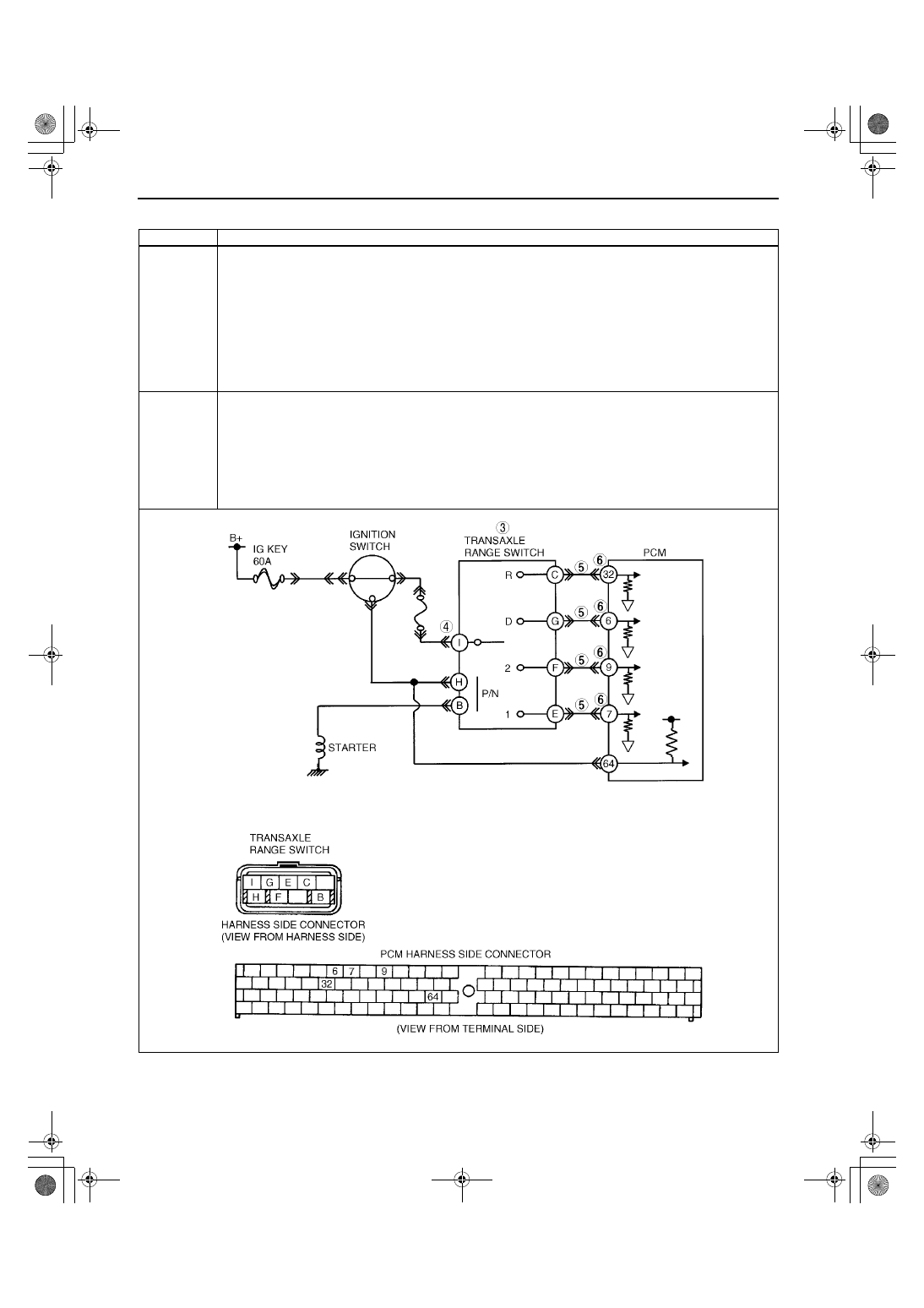
05–02–16
DTC P0706
A3U050201030W08
DTC P0706
Transaxle range (TR) switch circuit malfunction (open circuit)
DETECTION
CONDITION
•
When all conditions below satisfied and 100 seconds or more have passed.
— D, 2, 1range and R range switch not input.
— Engine speed 530 rpm or above.
— Vehicle speed 20 km/h {12 mph} or above.
Diagnostic support note:
•
This is a continuous monitor (CCM).
•
MIL illuminates if PCM detects the above malfunction conditions during two consecutive drive cycles.
•
PENDING CODE is available.
•
FREEZE FRAME DATA is available.
•
O/D OFF indicator light flashes.
•
DTC is stored in the PCM memory.
POSSIBLE
CAUSE
•
Charging system malfunction
•
TR switch malfunction
•
TR switch misadjustment
•
Open circuit between TR switch terminal G and PCM terminal 6
•
Open circuit between TR switch terminal F and PCM terminal 9
•
Open circuit between TR switch terminal E and PCM terminal 7
•
Open circuit between TR switch terminal I and dash harness (JB-04) terminals
•
Damaged connectors between TR switch and PCM
•
PCM malfunction
1712-1U-01G(05-02).fm 16 ページ 2001年6月29日 金曜日 午後4時35分