Mazda Protege 5. Manual - part 215


  Index      Mazda     Mazda Protege 5 - service repair manual 2002 year


Search            


Content   ..  213  214  215  216   ..


Mazda Protege 5. Manual - part 215


PARKING BRAKE SYSTEM 

04–12–2

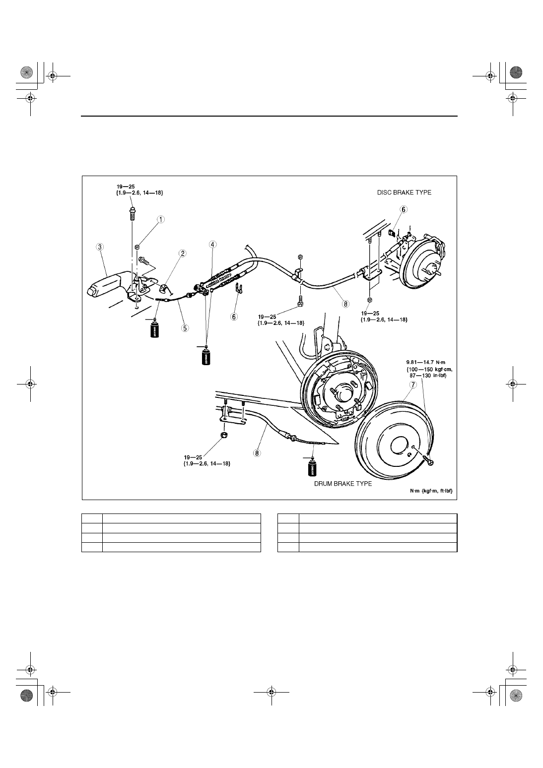
PARKING BRAKE (LEVER TYPE) REMOVAL/INSTALLATION

A3U041244000W04

1. Remove the rear console. (See 09–17–5 CONSOLE REMOVAL/INSTALLATION.)
2. Remove the exhaust pipe insulator bolts.
3. Remove in the order indicated in the table.
4. Install in the reverse order of removal.
5. Adjust the parking brake stroke. (See 04–12–1 PARKING BRAKE (LEVER TYPE) ADJUSTMENT.)

.

End Of Sie

A3U0412W002

1

Adjusting nut

2

Parking brake switch

3

Parking brake lever

4

Return spring

5

Front cable and equalizer

6

Clip

7

Brake drum

8

Parking brake cable

1712-1U-01G(04-12).fm  2 ページ  2001年6月29日 金曜日 午前10時3分

ANTILOCK BRAKE SYSTEM 

04–13–1

04–13

04–13

ANTILOCK BRAKE SYSTEM

ABS LOCATION INDEX . . . . . . . . . . . . .  04–13–1
ABS SYSTEM DIAGRAM . . . . . . . . . . . .  04–13–2
ABS HYDRAULIC UNIT (HU)/

CONTROL MODULE (CM) 
SYSTEM INSPECTION . . . . . . . . . . . . .  04–13–3

System Inspection . . . . . . . . . . . . . . . .  04–13–3
Using the SSTs  . . . . . . . . . . . . . . . . . .  04–13–3
Without using the SSTs . . . . . . . . . . . .  04–13–4

ABS HYDRAULIC UNIT (HU)/

CONTROL MODULE (CM) 
REMOVAL/INSTALLATION . . . . . . . . .  04–13–5

Connector Removal Note. . . . . . . . . . .  04–13–6
ABS HU/CM Removal/Installation Note 04–13–6
Connector Installation Note . . . . . . . . .  04–13–6

ABS HYDRAULIC UNIT (HU)/

CONTROL MODULE (CM) 
INSPECTION . . . . . . . . . . . . . . . . . . . . .  04–13–6

Terminal Voltage Table (Reference) . . . 04–13–6
Inspection Using An Oscilloscope 

(Reference) . . . . . . . . . . . . . . . . . . . . . 04–13–8

FRONT ABS WHEEL-SPEED SENSOR 

REMOVAL/INSTALLATION . . . . . . . . . . 04–13–9

FRONT/REAR ABS WHEEL-SPEED 

SENSOR INSPECTION  . . . . . . . . . . . . . 04–13–9

Visual Inspection . . . . . . . . . . . . . . . . . . 04–13–9
Clearance Inspection  . . . . . . . . . . . . . . 04–13–9
Resistance Inspection . . . . . . . . . . . . . . 04–13–9
Voltage Inspection. . . . . . . . . . . . . . . . . 04–13–10
Voltage Pattern Inspection  . . . . . . . . . . 04–13–10

REAR ABS WHEEL-SPEED SENSOR 

REMOVAL/INSTALLATION . . . . . . . . . . 04–13–10

End of Toc

ABS LOCATION INDEX

A3U041343000W01

.

End Of Sie

Z3U0413W101

1

ABS HU/CM
(See 04–13–3 ABS HYDRAULIC UNIT (HU)/
CONTROL MODULE (CM) SYSTEM INSPECTION)
(See 04–13–5 ABS HYDRAULIC UNIT (HU)/
CONTROL MODULE (CM) REMOVAL/
INSTALLATION)
(See 04–13–6 ABS HYDRAULIC UNIT (HU)/
CONTROL MODULE (CM) INSPECTION)

2

ABS wheel-speed sensor (front)
(See 04–13–9 FRONT ABS WHEEL-SPEED 
SENSOR REMOVAL/INSTALLATION)
(See 04–13–9 FRONT/REAR ABS WHEEL-SPEED 
SENSOR INSPECTION)

3

ABS wheel-speed sensor (rear)
(See 04–13–10 REAR ABS WHEEL-SPEED 
SENSOR REMOVAL/INSTALLATION)
(See 04–13–9 FRONT/REAR ABS WHEEL-SPEED 
SENSOR INSPECTION)

1712-1U-01G(04-13).fm  1 ページ  2001年6月29日 金曜日 午前10時4分

ANTILOCK BRAKE SYSTEM 

04–13–2

ABS SYSTEM DIAGRAM

A3U041343000W02

End Of Sie

A3U0402W001

1712-1U-01G(04-13).fm  2 ページ  2001年6月29日 金曜日 午前10時4分

ANTILOCK BRAKE SYSTEM 

04–13–3

04–13

ABS HYDRAULIC UNIT (HU)/CONTROL MODULE (CM) SYSTEM INSPECTION

A3U041343780W01

System Inspection
Preparation

1. Verify that the battery is fully charged. With the ignition switch on, verify that the ABS and BRAKE system 

warning lights goes out after 3 seconds.

2. If the lights stays on after 3 seconds, the ABS HU/CM detects a failure. Follow the troubleshooting procedures.
3. Turn the ignition switch off.
4. On level ground, jack up the vehicle and support it evenly on safety stands. Shift the transaxle to N position.
5. Release the parking brake.
6. Rotate the wheels by hand, and inspect for brake drag.

Using the SSTs

1. Perform the “Preparation.”
2. Connect the SSTs (WDS or equivalent) to the 

data link connector-2 (DLC-2).

3. Set up an active command mode inspection 

according to the combination of commands 
below. (See 04–02–3 ABS ON-BOARD 
DIAGNOSTIC.)

The chart above shows an example of a right wheel inspection.

Note

When working with two people, one should press on the brake pedal, the other should attempt to rotate 
the wheel being inspected.

4. Send the command while pressing on the brake pedal and attempting to rotate the wheel being inspected.
5. When pressure is being maintained, and click sound indicating the solenoid is operating comes from the ABS 

HU/CM, confirm that the wheel does not rotate. When pressure is being reduced, and click sound indicating the 
solenoid is operating comes from the ABS HU/CM, confirm that the wheel rotates, even though the brake pedal 
is being depressed.

Note

To protect the ABS HU/CM, the solenoid valve used for simulations and the ABS motor stay on for 10 
seconds
 each time they are switched on.

Performing the inspections above determines the following.
— The ABS HU/CM brake lines are normal.
— The ABS HU/CM hydraulic system is not significantly abnormal.
— The ABS HU/CM wiring is normal.

However, the following items cannot be checked.
— ABS HU/CM input system harness and parts
— Extremely small leaks in the ABS HU/CM internal hydraulic system
— Unusual intermittent occurrences in the above items

X3U101WA1

OPERATION

COMMAND NAME

COMMAND TYPE

PMP_MOTOR

RF_OUTLET

RF_INLET

ABS_POWER

Pressure retention

OFF

OFF

ON

ON

Manual

Pressure reduction

ON

ON

ON

ON

1712-1U-01G(04-13).fm  3 ページ  2001年6月29日 金曜日 午前10時4分


Content   ..  213  214  215  216   ..