Mazda Protege 5. Manual - part 213


  Index      Mazda     Mazda Protege 5 - service repair manual 2002 year


Search            


Content   ..  211  212  213  214   ..


Mazda Protege 5. Manual - part 213


CONVENTIONAL BRAKE SYSTEM 

04–11–21

04–11

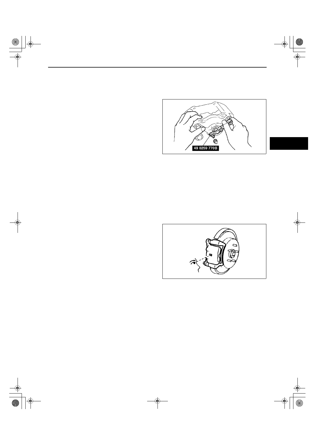
Bleeder Screw Assembly Note

1. Assemble the bleeder screw to the caliper using the SST.

Tightening torque

6.9—9.8 N·m {70—100 kgf·cm, 61—86 in·lbf}

End Of Sie

REAR BRAKE (DISC) INSPECTION

A3U041126980W01

Brake Judder Repair Hint
(See 04–11–14 Brake Judder Repair Hint.)

Disc Pad Thickness Inspection

1. Jack up the rear of the vehicle and support it on safety stands.
2. Remove the wheel and tires.
3. Look through the caliper inspection hole and inspect the remaining thickness of the pads.

Replace the pads as a set (right and left wheels) if either is less than the minimum thickness.

Minimum thickness

1.0 mm {0.039 in}

Disc Plate Thickness Inspection

1. Measure the thickness of the disc plate.

If the thickness is not within the specification, replace the disc plate.

Caution

••••

When it is necessary to machine the disc plate, and the disc plate is removed from the vehicle 
then machined, excessive runout may result. Machine the disc plate which is installed on the 
vehicle.

Minimum

8 mm {0.31 in}

Minimum thickness after machining by using a brake lathe on-vehicle

8.8 mm {0.35 in}

End Of Sie

X3U411WB0

W6U411WB7

1712-1U-01G(04-11).fm  21 ページ  2001年6月29日 金曜日 午前10時3分

CONVENTIONAL BRAKE SYSTEM 

04–11–22

REAR BRAKE (DISC) REMOVAL/INSTALLATION

A3U041126980W02

1. Remove in the order indicated in the table.
2. Install in the reverse order of removal.
3. After installation, depress the pedal several times, rotate the wheel by hand, and verify that the brake does not 

drag.

.

Disc Pad Installation Note

1. Turn the manual adjustment gear 

counterclockwise with an Allen wrench to pull the 
brake caliper piston inward. (Turn until it stops.)

2. Install the disc pads.
3. Turn the manual adjustment gear clockwise until 

the brake pads just touch the disc plate. Turn the 
manual adjustment gear back 1/3-turn.

End Of Sie

A3U0411W101

1

Parking brake cable, clip

2

Flexible hose

3

Screw plug

4

Lock bolt

5

Caliper

6

Disc pad
(See 04–11–22 Disc Pad Installation Note)

7

Shim

8

Guide plate

9

Mounting support

10

Disc plate
(See 04–11–18 Disc Plate Removal Note)
(See 04–11–18 Disc Plate Installation Note)

W6U411WB9

1712-1U-01G(04-11).fm  22 ページ  2001年6月29日 金曜日 午前10時3分

CONVENTIONAL BRAKE SYSTEM 

04–11–23

04–11

DISC PAD (REAR) REPLACEMENT

A3U041126630W01

1. Remove in the order indicated in the table.
2. Install in the reverse order of removal.

.

End Of Sie

Z3U0411W009

1

Parking brake cable, clip

2

Screw plug

3

Lock bolt

4

Disc pad
(See 04–11–22 Disc Pad Installation Note)

5

Shim

6

Guide plate

1712-1U-01G(04-11).fm  23 ページ  2001年6月29日 金曜日 午前10時3分

CONVENTIONAL BRAKE SYSTEM 

04–11–24

CALIPER (REAR) DISASSEMBLY/ASSEMBLY

A3U041126990W01

1. Disassemble in the order indicated in the table.
2. Assemble in the reverse order of disassembly.

.

Piston Disassembly Note

Turn the adjustment gear clockwise with an Allen 
wrench to remove the piston from the adjustment 
gear. (Turn the adjustment gear until it becomes 
easy to turn.)

Z3U0411W010

1

Screw plug

2

Dust seal

3

Piston
(See 04–11–24 Piston Disassembly Note)
(See 04–11–25 Piston Assembly Note)

4

Manual adjustment gear

5

Snap ring

6

Adjusting bolt

7

O-ring

8

Connecting link

9

Piston seal
(See 04–11–20 Piston Seal Disassembly Note)

10

Spring

11

Operating lever

12

Boot

13

Bleeder screw

14

Boot

15

Boot

16

Caliper body

W6U411WBC

1712-1U-01G(04-11).fm  24 ページ  2001年6月29日 金曜日 午前10時3分


Content   ..  211  212  213  214   ..