Mazda Protege 5. Manual - part 211


  Index      Mazda     Mazda Protege 5 - service repair manual 2002 year


Search            


Content   ..  209  210  211  212   ..


Mazda Protege 5. Manual - part 211


CONVENTIONAL BRAKE SYSTEM 

04–11–13

04–11

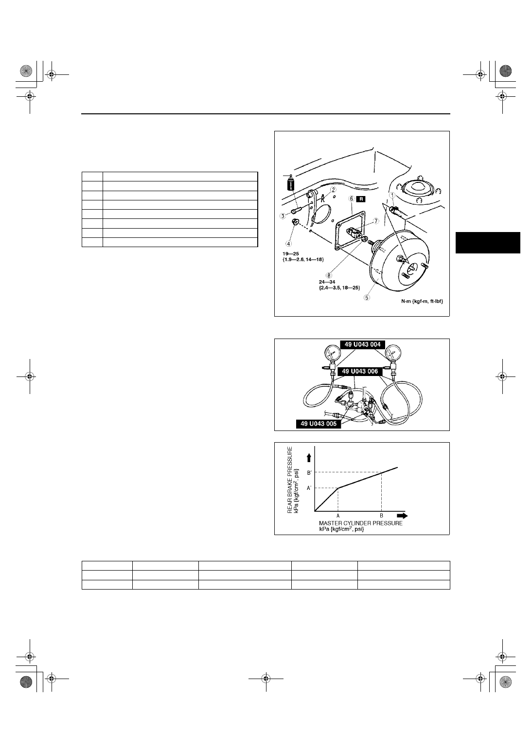
POWER BRAKE UNIT REMOVAL/INSTALLATION

A3U041143800W02

1. Remove the battery and battery cover.
2. Remove the master cylinder. (See 04–11–6 

MASTER CYLINDER REMOVAL/
INSTALLATION.)

3. Remove in the order indicated in the table.

4. Install in the reverse order of removal.

End Of Sie

DUAL PROPORTIONING VALVE (WITHOUT ABS) INSPECTION

A3U041143900W01

1. Connect the SSTs to the brake pipes as shown in 

the figure.

2. Bleed the air from the brake system.

3. Measure the fluid pressure of the master cylinder 

and the rear brake.

If not within the specification, replace the dual 
proportioning valve.

Fluid pressure

kPa {kgf/cm

2

, psi}

End Of Sie

1

Vacuum hose

2

Snap pin

3

Clevis pin

4

Nut

5

Power brake unit

6

Gasket

7

Fork

8

Nut

X3U411WAK

X3U411WAL

A3U0411W003

Engine type

A

A'

B

B'

ZM

2,900 {30, 430}

2,900 {30, 430}

±

200 {2, 30}

5,900 {60, 850}

3,800 {39, 550}

±

300 {3, 40}

FS

3,400 {35, 500}

3,400 {35, 500}

±

300 {3, 40}

5,900 {60, 850}

4,200 {42.5, 600}

±

400 {4, 60}

1712-1U-01G(04-11).fm  13 ページ  2001年6月29日 金曜日 午前10時3分

CONVENTIONAL BRAKE SYSTEM 

04–11–14

DUAL PROPORTIONING VALVE (WITHOUT ABS) AND BRAKE PIPE JOINT (WITH ABS) REPLACEMENT

A3U041143900W02

1. Remove in the order indicated in the table.
2. Install in the reverse order of removal.

.

Dual Proportioning Valve (Without ABS) or Brake Pipe Joint (With ABS) Installation Note

1. Install the dual proportioning valve so that the R 

mark faces the left side of the vehicle.

End Of Sie

FRONT BRAKE (DISC) INSPECTION

A3U041133980W01

Brake Judder Repair Hint
Description

1. Brake judder concern has the following 3 characteristics:

Steering wheel vibration

1. Steering wheel vibrates in the direction of its rotation. This characteristic is most noticeable when applying 

brakes at a vehicle speed of 100—140 km/h {62.1—86.8 mph}.

Floor vibration

1. When applying brakes, the vehicle body shakes back and forth. The seriousness of shake is not influenced by 

vehicle speed.

Z3U0411W001

1

Brake pipe

2

Bolt

3

Dual proportioning valve (without ABS) or brake 
pipe joint (with ABS)
(See 04–11–14 Dual Proportioning Valve (Without 
ABS) or Brake Pipe Joint (With ABS) Installation 
Note)

X3U411WAP

1712-1U-01G(04-11).fm  14 ページ  2001年6月29日 金曜日 午前10時3分

CONVENTIONAL BRAKE SYSTEM 

04–11–15

04–11

Brake pedal vibration

1. When applying brakes, a pulsating force tries to push the brake pad back occurs. The pulsation is transmitted 

to the brake pedal.

2. The following are the main possible causes of brake judder:

Due to an excessive runout (side-to-side wobble) of disc plate, the thickness of disc plate is uneven.

1. If the runout is more than 0.05 mm {0.002 in} 10 mm {0.39 in} from the disc plate edge, an uneven wear 

occurs on the disc plate because the pad contacts the plate unevenly.

2. If the runout is less than 0.05 mm {0.002 in}, uneven wear does not occur.

The disc plate is deformed by heat.

1. Repeated panic braking may raise the temperature in some portions of disc plate by approximately 1,000 

°°°°

{1,832 

°°°°

F}. This results in deformed disc plate.

Due to corrosion, the thickness and friction coefficient of disc plate change.

1. If a vehicle is parked under damp conditions for a long time, corrosion occurs on the friction surface of disc 

plate.

2. The thickness of corrosion is uneven and sometimes appears like a wave pattern, which changes the friction 

coefficient and causes a reaction force.

Inspection and repair procedure

Y3U411WA4

1712-1U-01G(04-11).fm  15 ページ  2001年6月29日 金曜日 午前10時3分

CONVENTIONAL BRAKE SYSTEM 

04–11–16

Lateral runout inspection

1. To secure the disc plate and the hub, tighten the hub nuts upside down or insert a washer (thickness 10 mm 

{0.39 in}, inner diameter more than 12 mm {0.47 in}) between the hub bolt and the hub nut.

Note

The component parts of the SST (49 B017 001 or 49 G019 003) can be used as a suitable washer.

2. After tightening all the hub nuts to the same torque, put the dial gauge on the friction surface of disc plate 10 

mm {0.39 in} from the disc plate edge.

3. Rotate the disc plate one time and measure the runout.

Runout limit

0.05 mm {0.002 in}

Thickness variation inspection

1. Clean the disc plate-to-pad friction surface using a brake cleaner.
2. Measure the points indicated in the illustration 

using a caliper (micrometer).

3. Subtract the minimum value from the maximum, 

and if the result is not within specification, 
machine the disc plate using a lathe.

Thickness variation limit

0.015 mm {0.00059 in}

Warning

••••

Do not exceed minimum disc plate 
thickness.

Disc Plate Thickness Inspection

Caution

••••

Excessive runout may result if the disc plate is removed from the vehicle then machined. Machine 
the disc plate while installed on the vehicle.

1. Measure the thickness of the disc plate.

If the thickness is not within the specification, replace the disc plate.

Minimum

ZM: 20 mm {0.78 in}
FS: 22 mm {0.87 in}

Minimum thickness after machining using a brake lathe on-vehicle

ZM: 20.8 mm {0.82 in}
FS: 22.8 mm {0.90 in}

Disc Pad Thickness Inspection

1. Jack up the front of the vehicle and support it with safety stands.
2. Remove the wheel and tires.
3. Verify the remaining thickness of the pads.

Minimum thickness

ZM: 1.5 mm {0.059 in} min.
FS: 2.0 mm {0.079 in} min.

4. Replace the pads as a set: right and left wheels, if 

either one is at or less than the minimum 
thickness.

End Of Sie

X3U411WAR

X3U411WAS

1712-1U-01G(04-11).fm  16 ページ  2001年6月29日 金曜日 午前10時3分


Content   ..  209  210  211  212   ..