Mazda Protege 5. Manual - part 209


  Index      Mazda     Mazda Protege 5 - service repair manual 2002 year


Search            


Content   ..  207  208  209  210   ..


Mazda Protege 5. Manual - part 209


CONVENTIONAL BRAKE SYSTEM 

04–11–5

04–11

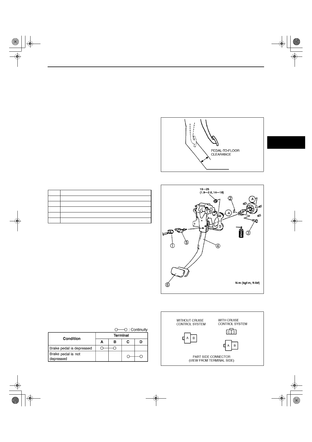
Pedal-to-floor Clearance Inspection

1. Start the engine and depress the brake pedal with a force of 588 N {60 kgf, 132 lbf}
2. Verify that the distance from the floor panel to the pedal pad center is as specified when the pedal is 

depressed.

If the distance is less than specified, check for the air in brake system.

Specification

ZM : 88 mm {3.5 in} min.
FS : 84 mm {3.3 in} min.

End Of Sie

BRAKE PEDAL REMOVAL/INSTALLATION

A3U041143300W02

1. Remove in the order indicated in the table.

2. Install in the reverse order of removal.

End Of Sie

BRAKE SWITCH INSPECTION

A3U041166490W01

1. Disconnect the brake switch connector.
2. Inspect for continuity between the terminals of the 

brake switch connector using the ohmmeter.

If not as specified, replace the brake switch.

End Of Sie

X3U411WA5

1

Brake switch connector

2

Spring pin

3

Clevis pin

4

Brake pedal

5

Brake switch

6

Pedal pad

X3U411WA6

A3U0411W001

Y3U411WA8

1712-1U-01G(04-11).fm  5 ページ  2001年6月29日 金曜日 午前10時3分

CONVENTIONAL BRAKE SYSTEM 

04–11–6

MASTER CYLINDER REMOVAL/INSTALLATION

A3U041143400W01

1. Remove in the order indicated in the table.

2. Install in the reverse order of removal.

Master Cylinder Installation Note
FS

1. Turn the nut of the SST clockwise to fully retract the SST gauge rod. Attach the SST to the power brake unit.

Tightening torque

9.9—15 N·m {1.0—1.6 kgf·m, 7.3—11 ft·lbf}

2. Apply a 66.7 kPa {500 mmHg, 19.7 inHg} 

vacuum by using a vacuum pump.

3. Turn the adjusting nut of the SST 

counterclockwise until the gauge rod just contacts 
the push rod end of the power brake unit. Push 
lightly on the end of the gauge rod to be sure it is 
seated. Verify that there is no gap between the 
adjusting nut and SST body.

4. Remove the SST from the power brake unit 

without disturbing the adjusting nut. Set the SST 
onto the master cylinder as shown in the figure.

Caution

••••

When pushing the SST gauge rod into 
the master cylinder piston, only use 
enough pressure to push the rod to the 
bottom of the piston. If too much 
pressure is applied, a false reading 
will occur.

1

Brake fluid level sensor connector

2

Brake pipe

3

Hose (MTX)

4

Master cylinder
(See 04–11–6 Master Cylinder Installation Note

X3U411WA9

Z5U0411W130

Z5U0411W131

1712-1U-01G(04-11).fm  6 ページ  2001年6月29日 金曜日 午前10時3分

CONVENTIONAL BRAKE SYSTEM 

04–11–7

04–11

5. Push lightly on the end of the SST gauge rod to 

be sure it has contacted the bottom of the master 
cylinder piston, but do not push so hard that the 
piston moves. Note any clearance between the 
SST body and the adjusting nut (clearance B) or 
between the body and the master cylinder 
(clearance C).

Adjusting the push rod clearance at B

Note

The threads of the push rod are specially designed so that the bolt becomes harder to turn past a certain 
point. This is to prevent the bolt from coming loose. Turn the bolt only within this range when adjusting.

1. Push lightly on the end of the SST gauge rod, and 

measure the clearance between the adjusting nut 
and the SST body.

2. Using the SST, turn the nut to lengthen the power 

brake unit push rod an amount equal to the sum 
substracting 0.1—0.4 mm {0.004—0.016 in} from 
the clearance measured at B.

Measurement

Push rod

Clearance at (B)

Too short

Clearance at (C)

Too long

No clearance at (B) or (C)

Z5U0411W132

Z5U0411W133

Z5U0411W134

1712-1U-01G(04-11).fm  7 ページ  2001年6月29日 金曜日 午前10時3分

CONVENTIONAL BRAKE SYSTEM 

04–11–8

Adjusting the push rod clearance at C or no clearance at B or C

Note

The threads of the push rod are specially designed so that the bolt becomes harder to turn past a certain 
point. This is to prevent the bolt from coming loose. Turn the bolt only within this range when adjusting.

1. Measure and record height D1 of the gauge rod.
2. Turn the adjusting nut until the SST body sets 

evenly on the master cylinder. (Turn only enough 
for the body to touch.)

3. Measure and record height D2 of the gauge rod.

4. Subtract D1 from D2 and add 0.1—0.4 mm 

{0.004—0.016 in}. Using the SST, turn the nut to 
shorten the power booster push rod an amount 
equal to the sum.

ZM

1. Place the SST atop the master cylinder. Turn the 

adjusting bolt until it touches the bottom of the 
push rod hole in the piston.

2. Apply 66.7 kPa {500 mmHg, 19.7 inHg} vacuum 

to the power brake unit using a vacuum pump.

Z5U0411W135

Z5U0411W136

Z5U0411W134

X3U411WAA

1712-1U-01G(04-11).fm  8 ページ  2001年6月29日 金曜日 午前10時3分


Content   ..  207  208  209  210   ..