Mazda Protege 5. Manual - part 207
 

  Index      Mazda     Mazda Protege 5 - service repair manual 2002 year


Search            


Content   ..  205  206  207  208   ..


Mazda Protege 5. Manual - part 207


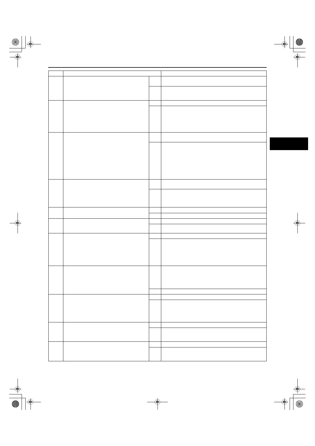
SYMPTOM TROUBLESHOOTING 

04–03–11

04–03

End Of Sie

5

CONFIRM THAT MALFUNCTION SYMPTOM 
DO NOT REOCCUR AFTER ABS HU/CM 
CONNECTOR TERMINAL W IS CONNECTED

Do ABS warning light go out after more than 
4 seconds
 with ignition switch on?

Yes

Temporary poor connection at terminal.
Inspect ABS HU/CM connector and terminal.

No

Go to next step.

6

CHECK FOR OPEN CIRCUITS IN ABS HU/CM

Disconnect ABS HU/CM. Connect the SST 
(49 G066 001) (vehicle harness side only).

Use the SST connector to ground ABS 
warning light terminal W to body ground. 
Does ABS warning light go out with ignition 
switch on?

Yes

Replace ABS HU/CM (open circuit in ABS HU/CM).

No

Go to next step.

*7

CHECK TO SEE WHETHER MALFUNCTION 
IS IN WIRING HARNESS (LACK OF 
CONTINUITY BETWEEN INSTRUMENT 
CLUSTER AND ABS HU/CM) OR 
INSTRUMENT CLUSTER (OPEN CIRCUIT OR 
SHORT TO GROUND)

Disconnect instrument cluster.

Is there continuity between following SST 
connector terminal W and instrument cluster 
connector (16-pin) terminal 2B?

Yes

Replace instrument cluster (open circuit or ground to short 
in instrument cluster).

No

Repair wiring harness between ABS HU/CM (terminal W) 
and instrument cluster.

8

INSPECT ABS HU/CM IGINITION POWER 
SUPPLY SYSTEM (TERMINAL Z)

Check the voltage for PID/DATA monitor 
ABS_VOLT item.
Specification: above 10V

Is voltage within specification?

Yes

Replace ABS HU/CM (open circuit or short in ground circuit 
in ABS HU/CM).

No

Go to next step.

9

INSPECT BATTERY

Is battery voltage normal?

Yes

Go to next step

No

Inspect battery and charging system

10

INSPECT CHARGING SYSTEM

Is battery voltage normal with electrical load 
(A/C, headlights, etc) on and engine idling?

Yes

Go to next step

No

Inspect charging system (drive belt tension, generator, etc).

*11

INSPECT WIRING HARNESS BETWEEN ABS 
HU/CM POWER SUPPLY AND ABS HU/CM 
FOR CONTINUITY

Disconnect ABS HU/CM. Connect SST (49 
G066 001) (vehicle harness side only).

Is voltage approximately 12V at SST 
connector terminal Z?

Yes

Go to next step.

No

Repair wiring harness between fuse block and ABS HU/CM

*12

INSPECT WIRING HARNESS BETWEEN ABS 
HU/CM AND GROUND FOR CONTINUITY

Turn ignition switch to LOCK

Is there continuity between SST connector 
terminal AA and ground?

Yes

If a communication error message is displayed on WDS or 
equivalent in Step 1 inspection, go to next step.
If a communication error message is not displayed on WDS 
or equivalent in Step 1 inspection, trouble shooting is 
completed.

No

Repair wiring harness between ABS HU/CM and ground.

*13

INSPECT WIRING HARNESS BETWEEN ABS 
HU/CM AND DLC-2 FOR CONTINUITY

Disconnect ABS HU/CM. Connect the SST 
(49 G066 001) (vehicle harness side only).

Is there continuity between SST connector 
terminal T and DLC-2?

Yes

Go to next step.

No

Repair wiring harness between ABS HU/CM and DLC-2.

*14

INSPECT WIRING HARNESS BETWEEN ABS 
HU/CM AND DLC-2 FOR SHORT TO B+

Is voltage approximately 12 V at SST 
connector terminal T?

Yes

Repair wiring harness between ABS HU/CM and DLC-2.

No

Go to next step.

*15

INSPECT WIRING HARNESS BETWEEN ABS 
HU/CM AND DLC-2 FOR SHORT TO GROUND

Is there continuity between SST connector 
terminal T and ground?

Yes

Repair wiring harness between ABS HU/CM and DLC-2.

No

Replace ABS HU/CM (communication circuit malfunction in 
ABS HU/CM).

STEP

INSPECTION

ACTION

1712-1U-01G(04-03).fm  11 ページ  2001年6月29日 金曜日 午前10時2分

SYMPTOM TROUBLESHOOTING 

04–03–12

NO.6 BRAKE SYSTEM WARNING LIGHT STAYS ON

A3U040343000W10

When performing an asterisked (*) troubleshooting inspection, shake the wiring harness and connectors while 
performing the inspection to discover whether poor contact points are the cause of any intermittent 
malfunctions. If there is a problem, check to make sure connectors, terminals and wiring harness are 
connected correctly and undamaged.

Diagnostic procedure

6

BRAKE system warning light stays ON

DESCRIPTION

Brake system warning light stays on more than 4 seconds with ignition switch on. (Parking brake is 
released.)

POSSIBLE 

CAUSE

Warning light circuit open or shorted to ground in ABS HU/CM

Short to ground in circuit in parking brake switch and/or brake fluid level sensor

STEP

INSPECTION

ACTION

1

INSPECT BRAKE FLUID LEVEL

Is brake fluid level okay?

Yes

Go to next step.

No

Add brake fluid.

2

INSPECT WIRING HARNESS BETWEEN ABS 
HU/CM AND DLC-2 FOR CONTINUITY AND 
SHORTS

Inspect the following items using WDS or 
equivalent.
— BRAKE_LMP (BRAKE system warning 

light)

Is error message displayed regarding 
communication between ABS HU/CM and 
WDS or equivalent?

Yes

If a communication error message is displayed even after 
inspecting according to procedures displayed on the WDS 
or equivalent, go to Step 8.

No

Go to next step.

3

INSPECT PID/DATA IN ABS HU/CM

Inspect BRAKE_LMP (BRAKE system 
warning light) using WDS or equivalent.

Is BRAKE_LMP is ON after more than 4 
seconds
 with ignition switch on?

Yes

Replace ABS HU/CM (open circuit or short to ground in ABS 
HU/CM).

No

Go to next step.

4

VERIFY THAT ABS HU/CM CONNECTOR 
TERMINAL X IS CONNECTED

Does malfunction symptom happen again 
when ABS HU/CM connector terminal X is 
shaken while the ignition switch is ON?.

Yes

Connect ABS HU/CM connector terminal X securely, then 
go to next step.

No

Go to Step 6.

5

CONFIRM THAT MALFUNCTION SYMPTOMS 
DO NOT RECCUR AFTER ABS HU/CM 
CONNECTOR TERMINAL X IS CONNECTED

Does BRAKE system warning light go out 
after more than 4 seconds with ignition 
switch on?

Yes

Temporary poor connection at terminal.
Inspect ABS HU/CM connector and terminal.

No

Go to next step.

*6

CHECK FOR OPEN CIRCUITS IN ABS HU/CM

Disconnect ABS HU/CM. Connect the SST 
(49 G066 001) (vehicle harness side only).

Use the SST connector to ground BRAKE 
system warning light terminal X to body 
ground.

Does BRAKE system warning light go out 
with ignition switch on?

Yes

Replace ABS HU/CM (open circuit in ABS HU/CM).

No

Go to next step.

1712-1U-01G(04-03).fm  12 ページ  2001年6月29日 金曜日 午前10時2分

SYMPTOM TROUBLESHOOTING 

04–03–13

04–03

End Of Sie

NO.7 BRAKE SYSTEM MALFUNCTION

A3U040343000W11

Diagnostic procedure

End Of Sie

7

CHECK TO SEE WHETHER MALFUNCTION 
IS IN PARKING BRAKE SWITCH OR BRAKE 
FLUID LEVEL SENSOR, OR IN SOME OTHER 
PART

Disconnect the following in order:
1. Parking brake switch connector
2. Brake fluid level sensor connector

Does BRAKE system warning light go out 
with ignition switch on?

Yes

Replace parking brake switch and/or brake fluid level sensor 
(shorted on some internal part).

No

Perform the following inspections. Repair if necessary.

Open circuit in wiring harness between ABS HU/CM 
(terminal X) and instrument cluster (BRAKE system 
warning light)

Short to ground in wiring harness between instrument 
cluster (BRAKE system warning light) and parking brake 
switch.

Short to ground in wiring harness between instrument 
cluster (BRAKE system warning light) and brake fluid 
level sensor.

If above inspections are okay, replace instrument cluster 
(open or ground to short in instrument cluster).

*8

INSPECT WIRING HARNESS BETWEEN ABS 
HU/CM AND DLC-2 FOR CONTINUITY

Disconnect ABS HU/CM. Connect the SST 
(49 G066 001) (vehicle harness side only).

Is there continuity between SST connector 
terminal T and DLC-2?

Yes

Go to next step.

No

Repair wiring harness between ABS HU/CM and DLC-2.

*9

INSPECT WIRING HARNESS BETWEEN ABS 
HU/CM AND DLC-2 FOR SHORT TO B+

Is voltage approximately 12 V at SST 
connector terminal T?

Yes

Repair wiring harness between ABS HU/CM and DLC-2.

No

Go to next step.

*10

INSPECT WIRING HARNESS BETWEEN ABS 
HU/CM AND DLC-2 FOR SHORT TO GROUND

Is there continuity between SST connector 
terminal T and ground?

Yes

Repair wiring harness between ABS HU/CM and DLC-2.

No

Replace ABS HU/CM (communication circuit malfunction in 
ABS HU/CM).

STEP

INSPECTION

ACTION

7

BRAKE system malfunction

DESCRIPTION

There is a malfunction in system even though ABS warning light and BRAKE system warning light does 
not illuminate.

POSSIBLE 

CAUSE

There is a mechanical malfunction in system

STEP

INSPECTION

ACTION

1

CHECK FOR DTCS IN ABS HU/CM

Have DTCs been recorded in memory?

Yes

Perform inspection using appropriate DTC.

No

Go to next step.

2

INSPECT ABS HYDRAULIC UNIT

Perform “ABS hydraulic unit system 
inspection”.

Is system okay?

Yes

Inspect conventional brake system.

No

If wheels do not rotate:

Replace ABS HU/CM.

If wheels rotate but order in which wheels rotate is 
incorrect:

Inspect brake pipe passage to ABS HU/CM.

1712-1U-01G(04-03).fm  13 ページ  2001年6月29日 金曜日 午前10時2分

GENERAL PROCEDURES 

04–10–1

04–10

04–10

GENERAL PROCEDURES

PRECAUTION (BRAKES). . . . . . . . . . . .  04–10–1

Wheels and Tires Removal/Installation 04–10–1
Brake Lines Disconnection/Connection 04–10–1

Connectors Disconnection  . . . . . . . . . . 04–10–1
ABS Components Operations . . . . . . . . 04–10–1

End of Toc

PRECAUTION (BRAKES)

A3U041001020W01

Wheels and Tires Removal/Installation

1. The removal and installation procedures for the wheels and tires are not mentioned in this section. When a 

wheel is removed, tighten it to 89—117 N·m {9.0—12.0 kgf·m, 65.1—86.7 ft·lbf}.

Brake Lines Disconnection/Connection

Caution

••••

Brake fluid will damage painted surfaces. If brake fluid does get on a painted surface, wipe it off 
immediately.

1. Tighten the brake pipe flare nut using the SST (49 0259 770B). Be sure to modify the brake pipe flare nut 

tightening torque to allow for use of a torque wrench-SST combination. (See 00–00–15 Torque Formulas.)

If any brake line has been disconnected anytime during the procedure, add brake fluid, bleed the brakes, 
and inspect for leakage after the procedure has been completed.

Connectors Disconnection

1. Disconnect the negative battery cable before doing any work that requires handling of connectors. Reconnect 

the negative battery cable only after the work is completed.

ABS Components Operations

1. Make sure that there are no DTCs in the ABS memory after working on ABS components.

If there are any DTCs in the memory, clear them.

End Of Sie

1712-1U-01G(04-10).fm  1 ページ  2001年6月29日 金曜日 午前10時2分


Content   ..  205  206  207  208   ..