Mazda Protege 5. Manual - part 205


  Index      Mazda     Mazda Protege 5 - service repair manual 2002 year


Search            


Content   ..  203  204  205  206   ..


Mazda Protege 5. Manual - part 205


SYMPTOM TROUBLESHOOTING 

04–03–3

04–03

FOREWORD

A3U040343000W02

Before performing the steps in Symptom Troubleshooting, perform the On-board Diagnostic Test. To check the 
DTC, follow the OBD TEST steps.

End Of Sie

ABS

A3U040343000W03

Foreword

Before performing the steps in Symptom Troubleshooting, perform the On-board Diagnostic Inspection. To 
check the DTC, follow the DTC Inspection steps.

Precaution
When inspecting or servicing the ABS, note the following points:

1. The ABS warning light and/or BRAKE system warning light illuminate even when the system is normal.

*

1

: In cases where the light may illuminate, only when ABS HU/CM detects that a rear wheel’s speed sensor is 

malfunctioning.

*

2

: If battery voltage drops below about 9 to 10 V while vehicle speed is greater than 6 km/h {3.7 mph}, ABS 

HU/CM records DTC B1318 (DTC 63).

2. Precautions during servicing of ABS

The ABS is composed of electrical and mechanical parts. It is necessary to categorize malfunctions as being 
either electrical or hydraulic when performing troubleshooting.
(1) Malfunctions in electrical system

The ABS hydraulic unit and control module (ABS HU/CM) has an on-board diagnostic function. With 
this function, the ABS warning light and/or BRAKE system warning light will come on when there is a 
problem in the electrical system. Also, past and present malfunctions are recorded in the ABS HU/CM. 
This function can find malfunctions that do not occur during periodic inspections. Turn the ignition 
switch on by connecting the SST (WDS or equivalent) to the DLC-2 inside the Passenger comportment. 
Approximately 5 seconds later the stored malfunctions will be displayed in order of occurrence. To 
find out the causes of ABS malfunctions, use these on-board diagnostic results.

If a malfunction occurred in the past but is now normal, the cause is likely a temporary poor connection 
of the harness. The ABS HU/CM usually operates normally. Be careful when searching for the cause of 
malfunction.

After repair, it is necessary to erase the DTC from the ABS HU/CM memory. Also, if the ABS related 
parts have been replaced, verify that the no DTC has been displayed after repairs.

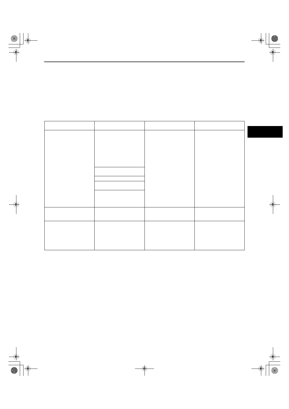
Warning lights that may 
illuminate

Cases in which the light 
may illuminate

Condition in which the light 
will go out

ABS and EBD control

ABS warning light

BRAKE system warning 
light (*

1

)

Under any of the following 
conditions:

When the front wheels are 
jacked up, stuck, or placed 
on a chassis roller, and 
only the front wheel ABS 
wheel speed sensors are 
spun for more than 20 
seconds
.

After turning ignition switch 
OFF, vehicle is driven at 
speed greater than 10 km/h 
{6.2 mph}
 and normal 
operation is confirmed.

ABS: Cuts control.

EBD:
1. Cuts control, in cases 

where the light may 
illuminate, only when 
ABS HU/CM detects 
that a wheel speed 
sensor determines that 
more than 2 rear 
wheels are 
malfunctioning.

2. Operates control, if 

wheel speed sensor 
determines that more 
than 3 wheels are 
functioning correctly.

Parking brake is not fully 
released while driving.

Brake drag.

Sudden acceleration/ 
deceleration.

Left/ right or front/ rear tires 
are different. (Size, radius, tire 
pressure, or wear is other 
than that listed on tire label.)

ABS warning light

Battery voltage at ABS HU/
CM ignition terminal Z drops 
below about 9 to 10 V. (*

2

)

Battery voltage rises above 
about 10 V
.

ABS: Operates control.
EBD: Operates control.

ABS warning light

BRAKE system warning 
light 

Battery voltage at ABS HU/
CM ignition terminal Z drops 
below about 9 to 10 V. (*

2

)

Battery voltage rises above 
about 10 V
.
(Only BRAKE system warning 
light goes out.)
Battery voltage rises above 
about 10 V
. (Both warning 
lights go out)

ABS: Operates control.
EBD: Operates control.

1712-1U-01G(04-03).fm  3 ページ  2001年6月29日 金曜日 午前10時2分

SYMPTOM TROUBLESHOOTING 

04–03–4

After repairing the ABS wheel-speed sensor or ABS sensor rotor, or after replacing the ABS HU/CM 
(ABS motor or ABS motor relay or solenoid valve), the ABS warning light may not go off even when the 
ignition switch is turned on. In this case, drive the vehicle at a speed of more than 10 km/h {6.2 mph}
make sure the ABS warning light goes off, and then erase the DTC.

When repairing, if the ABS related connectors are disconnected and the ignition switch is turned on, the 
ABS HU/CM will mistakenly detect a fault and record it as a malfunction.

To protect the ABS HU/CM, make sure the ignition is off before connecting or disconnecting the ABS 
HU/CM connector.

To protect the terminal, use the SST (49 G066 001) when connecting the tester lead to the ABS HU/CM 
connector.

(2) Malfunctions in hydraulic system

Symptoms in a hydraulic system malfunction are similar to those in a conventional brake malfunction. 
However, it is necessary to determine if the malfunction is in an ABS component or the conventional 
brake system.

The ABS hydraulic unit contains delicate mechanical parts. If foreign materials get into the component, 
the ABS may fail to operate. Also, it will likely become extremely difficult to find the location of the 
malfunction in the event that the brakes operate but the ABS does not. Make sure foreign materials do 
not get inside when servicing the ABS (e.g. brake fluid replacement, pipe removal).

End Of Sie

SYMPTOM TROUBLESHOOTING

A3U040343000W04

ABS Symptom Troubleshooting

Verify the symptom, and perform troubleshooting according to the appropriate number.

No.

TROUBLESHOOTING ITEM

DESCRIPTION

PAGE

1

Neither ABS warning light nor BRAKE 
system warning light illuminate

Neither ABS warning light nor BRAKE 
system warning light illuminate with 
ignition switch on.

(See 04–03–5 NO.1 NEITHER 
ABS WARNING LIGHT NOR 
BRAKE SYSTEM WARNING 
LIGHT ILLUMINATE)

2

ABS warning light does not illuminate

ABS warning light does not illuminate 
with ignition switch on.

(See 04–03–6 NO.2 ABS 
WARNING LIGHT DOES NOT 
ILLUMINATE)

3

BRAKE system warning light does not 
illuminate

BRAKE system warning light does not 
illuminate with ignition switch on.

(See 04–03–7 NO.3 BRAKE 
SYSTEM WARNING LIGHT 
DOES NOT ILLUMINATE)

4

ABS warning light and BRAKE system 
warning light stay ON

Both ABS warning light BRAKE system 
warning light stay on more than 4 
seconds
 with ignition switch on.

(See 04–03–8 NO.4 ABS 
WARNING LIGHT AND 
BRAKE SYSTEM WARNING 
LIGHT STAY ON)

5

ABS warning light stays ON

ABS warning light stays on more than 4 
seconds
 with ignition switch on.

(See 04–03–10 NO.5 ABS 
WARNING LIGHT STAYS ON)

6

BRAKE system warning light stays ON BRAKE system warning light stays on 

more than 4 seconds with ignition 
switch on. (Parking brake is released)

(See 04–03–12 NO.6 BRAKE 
SYSTEM WARNING LIGHT 
STAYS ON)

7

BRAKE system malfunction

There is a malfunction in system even 
though ABS warning light and BRAKE 
system warning light does not illuminate.

(See 04–03–13 NO.7 BRAKE 
SYSTEM MALFUNCTION)

1712-1U-01G(04-03).fm  4 ページ  2001年6月29日 金曜日 午前10時2分

SYMPTOM TROUBLESHOOTING 

04–03–5

04–03

Quick Diagnosis Chart
Vehicles with ABS

End Of Sie

NO.1 NEITHER ABS WARNING LIGHT NOR BRAKE SYSTEM WARNING LIGHT ILLUMINATE

A3U040343000W05

When performing an asterisked (*) troubleshooting inspection, shake the wiring harness and connectors while 
performing the inspection to discover whether poor contact points are the cause of any intermittent 
malfunctions. If there is a problem, check to make sure connectors, terminals and wiring harness are 
connected correctly and undamaged.

Diagnostic procedure

Y3U403WA1

1

Neither ABS warning light nor BRAKE system warning light illuminate

DESCRIPTION

Neither ABS warning light nor BRAKE system warning light illuminate with ignition switch on.

POSSIBLE 

CAUSE

Warning light circuit and indicator light circuits open circuit or shorted to ground.

STEP

INSPECTION

ACTION

1

CHECK TO SEE WHETHER MALFUNCTION 
IS IN WARNING LIGHTS’ COMMON POWER 
SUPPLY OR OTHER WARNING LIGHTS AND 
INDICATOR LIGHTS

Do other warning and indicator lights 
illuminate when IG switch is turned ON?

Yes

Replace instrument cluster (open circuit in instrument 
cluster).

No

Go to next step.

1712-1U-01G(04-03).fm  5 ページ  2001年6月29日 金曜日 午前10時2分

SYMPTOM TROUBLESHOOTING 

04–03–6

End Of Sie

NO.2 ABS WARNING LIGHT DOES NOT ILLUMINATE

A3U040343000W06

When performing an asterisked (*) troubleshooting inspection, shake the wiring harness and connectors while 
performing the inspection to discover whether poor contact points are the cause of any intermittent 
malfunctions. If there is a problem, check to make sure connectors, terminals and wiring harness are 
connected correctly and undamaged.

Diagnostic procedure

2

CHECK TO SEE WHETHER MALFUNCTION 
IS IN WARNING LIGHTS’ COMMON GROUND 
OR TURN SIGNAL INDICATOR LIGHT

Turn ignition switch ON.

Turn signal switch ON.

Does turn signal indicator light in instrument 
cluster illuminate?

Yes

Replace instrument cluster (open circuit in instrument 
cluster).

No

Go to next step.

3

INSPECT INSTRUMENT CLUSTER POWER 
SUPPLY FUSE

Is instrument cluster ignition power supply 
fuse okay?

Yes

Go to next step.

No

Check for a short to ground on blown fuse's circuit.
Repair or replace as necessary.
Install appropriate amperage fuse.

*4

INSPECT WIRING HARNESS BETWEEN 
INSTRUMENT CLUSTER POWER SUPPLY 
AND INSTRUMENT CLUSTER FOR 
CONTINUITY

Turn ignition switch ON.

Measure voltage at instrument cluster 
connector (18-pin) terminal 1J.

Is voltage approximately 12V?

Yes

Go to next step

No

Repair wiring harness between fuse block and instrument 
cluster.

*5

CHECK TO SEE WHETHER MALFUNCTION 
(LACK OF CONTINUTY) IS IN WIRING 
HARNESS (BETWEEN INSTRUMENT 
CLUSTER AND GROUND) OR INSTRUMENT 
CLUSTER

Turn ignition switch to LOCK.

Disconnect instrument cluster connector.

Is there continuity between instrument 
cluster connector (18-pin) terminal 1D and 
ground?

Yes

Replace instrument cluster (open circuit in instrument 
cluster).

No

Repair wiring harness between instrument cluster and 
ground.

STEP

INSPECTION

ACTION

2

ABS warning light does not illuminate

DESCRIPTION

ABS warning light does not illuminate with ignition switch on.

POSSIBLE 

CAUSE

ABS warning light circuit open circuit or shorted to ground.

STEP

INSPECTION

ACTION

1

CHECK FOR SHORT TO GROUND IN ABS 
HU/CM

Disconnect ABS HU/CM connector and turn 
ignition switch on.

Does ABS warning light illuminate?

Yes

Replace ABS HU/CM (short to ground in ABS HU/CM).

No

Go to next step.

2

INSPECT ABS WARNING LIGHT BULB

Remove instrument cluster.

Inspect ABS warning light bulb.

Is it okay?

Yes

Go to next step.

No

Replace ABS warning light bulb.

1712-1U-01G(04-03).fm  6 ページ  2001年6月29日 金曜日 午前10時2分


Content   ..  203  204  205  206   ..