Mazda Protege 5. Manual - part 204


  Index      Mazda     Mazda Protege 5 - service repair manual 2002 year


Search            


Content   ..  202  203  204  205   ..


Mazda Protege 5. Manual - part 204


ON-BOARD DIAGNOSTIC 

04–02–18

End Of Sie

DTC B1342 (61)

A3U040243000W10

Diagnostic procedure

End Of Sie

DTC B1318 (63)

A3U040243000W11

Caution

••••

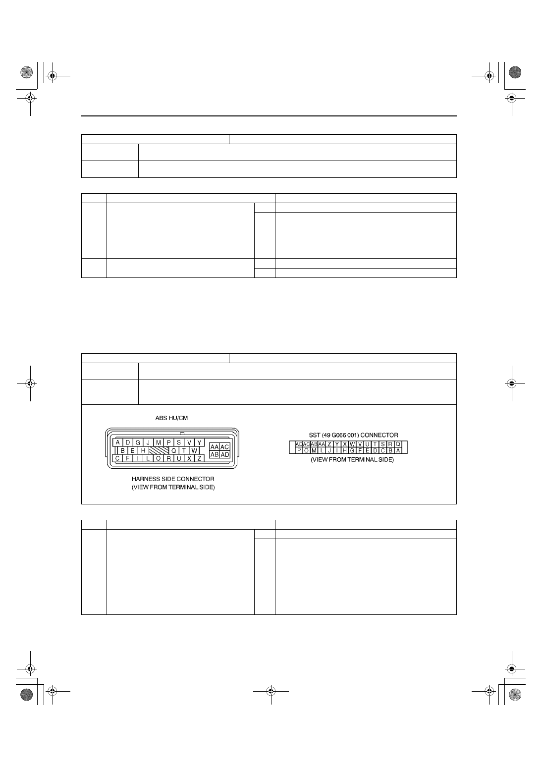
When attaching the tester lead to the ABS HU/CM or the ABS HU/CM harnesses connector the SST 
(49 G066 001) must be used. (See 04–13–6 ABS HYDRAULIC UNIT (HU)/CONTROL MODULE (CM) 
INSPECTION.)

Diagnostic procedure

DTC

B1342 (61)

ABS HU/CM (CM)

DETECTION 

CONDITION

The on-board diagnostic function detects computer malfunction.

POSSIBLE 

CAUSE

Malfunction of ABS HU/CM

STEP

INSPECTION

ACTION

1

VERIFY CURRENT STATUS OF 
MALFUNCTION

Clear DTC from memory.
(See 04–02–4 DTCs Clearing Procedure)

Start engine and drive vehicle at 10 km/h 
{6.2 mph}
 or above.

Is same DTC present?

Yes

Replace ABS HU/CM, then go to next step.

No

Go to next step.

2

VERIFY AFTER REPAIR PROCEDURE

Is there any other DTC present?

Yes

Go to applicable DTC inspection.

No

Troubleshooting completed.

DTC

B1318 (63)

ABS HU/CM power supply

DETECTION 

CONDITION

Voltage at Z terminal of ABS HU/CM drops below 10 V when driving vehicle.

POSSIBLE 

CAUSE

Low power supply

Battery and/or generator malfunction

Poor ground or open circuit of ground

STEP

INSPECTION

ACTION

1

INSPECT ABS HU/CM POWER SUPPLY 
CIRCUIT FOR OPEN CIRCUIT

Turn ignition key to OFF.

Disconnect ABS HU/CM connector.

Connect SST (adapter harness) to ABS HU/
CM connector (harness side) with ABS HU/
CM disconnected.

Start engine.

Measure voltage between terminal Z of SST 
(harness side) and ground.

Is voltage above 10 V?

Yes

Go to next step.

No

Go to Step 3.

1712-1U-01G(04-02).fm  18 ページ  2001年6月29日 金曜日 午前10時1分

ON-BOARD DIAGNOSTIC 

04–02–19

04–02

End Of Sie

2

INSPECT ABS HU/CM GROUND CIRCUIT 
FOR POOR GROUND AND OPEN CIRCUIT

Turn ignition key to OFF.

Measure resistance between terminal AA of 
SST and ground.

Is resistance within 0—1 ohm?

Yes

Go to Step 5.

No

If there is no continuity:

Repair or replace harness for open between ABS HU/
CM and ground, then go to Step 5.

If resistance is not within 0—1 ohm:

Repair or replace harness for poor ground then go to 
Step 5.

3

INSPECT BATTERY POWER

Inspect battery.
(See 01–50–1 ENGINE TECHNICAL DATA)

Is it okay?

Yes

Go to next step.

No

Replace battery, then go to Step 5.

4

INSPECT GENERATOR

Inspect generator.
(See 01–17–3 GENERATOR INSPECTION)

Is it okay?

Yes

Go to next step.

No

Repair or replace generator, then go to Step 5.

5

VERIFY TROUBLESHOOTING COMPLETED

Make sure to reconnected all disconnected 
connectors.

Clear DTC from memory.
(See 04–02–4 DTCs Clearing Procedure)

Is same DTC present?

Yes

Replace ABS HU/CM, then go to next step.

No

Go to next step.

6

VERIFY AFTER REPAIR PROCEDURE

Is there any other DTC present?

Yes

Go to applicable DTC inspection.

No

Troubleshooting completed.

STEP

INSPECTION

ACTION

1712-1U-01G(04-02).fm  19 ページ  2001年6月29日 金曜日 午前10時1分

SYMPTOM TROUBLESHOOTING 

04–03–1

04–03

04–03

SYMPTOM TROUBLESHOOTING

ABS SYSTEM DIAGRAM . . . . . . . . . . . .  04–03–2
FOREWORD . . . . . . . . . . . . . . . . . . . . . .  04–03–3
ABS . . . . . . . . . . . . . . . . . . . . . . . . . . . . .  04–03–3

Foreword  . . . . . . . . . . . . . . . . . . . . . . .  04–03–3
Precaution . . . . . . . . . . . . . . . . . . . . . .  04–03–3

SYMPTOM TROUBLESHOOTING . . . . .  04–03–4

ABS Symptom Troubleshooting . . . . . .  04–03–4
Quick Diagnosis Chart . . . . . . . . . . . . .  04–03–5

NO.1 NEITHER ABS WARNING 

LIGHT NOR BRAKE SYSTEM 
WARNING LIGHT ILLUMINATE . . . . . .  04–03–5

NO.2 ABS WARNING LIGHT DOES 

NOT ILLUMINATE. . . . . . . . . . . . . . . . .  04–03–6

NO.3 BRAKE SYSTEM WARNING 

LIGHT DOES NOT ILLUMINATE . . . . . . 04–03–7

NO.4 ABS WARNING LIGHT AND 

BRAKE SYSTEM WARNING LIGHT 
STAY ON  . . . . . . . . . . . . . . . . . . . . . . . . 04–03–8

NO.5 ABS WARNING LIGHT 

STAYS ON  . . . . . . . . . . . . . . . . . . . . . . . 04–03–10

NO.6 BRAKE SYSTEM WARNING 

LIGHT STAYS ON  . . . . . . . . . . . . . . . . . 04–03–12

NO.7 BRAKE SYSTEM 

MALFUNCTION  . . . . . . . . . . . . . . . . . . . 04–03–13

End of Toc

1712-1U-01G(04-03).fm  1 ページ  2001年6月29日 金曜日 午前10時2分

SYMPTOM TROUBLESHOOTING 

04–03–2

ABS SYSTEM DIAGRAM

A3U040343000W01

End Of Sie

A3U0402W001

1712-1U-01G(04-03).fm  2 ページ  2001年6月29日 金曜日 午前10時2分


Content   ..  202  203  204  205   ..