Mazda Protege 5. Manual - part 139


  Index      Mazda     Mazda Protege 5 - service repair manual 2002 year


Search            


Content   ..  137  138  139  140   ..


Mazda Protege 5. Manual - part 139


INTAKE-AIR SYSTEM [ZM]

01–13A–11

01–13A

VARIABLE TUMBLE CONTROL SYSTEM (VTCS) DELAY VALVE INSPECTION [ZM]

A3U011318800W04

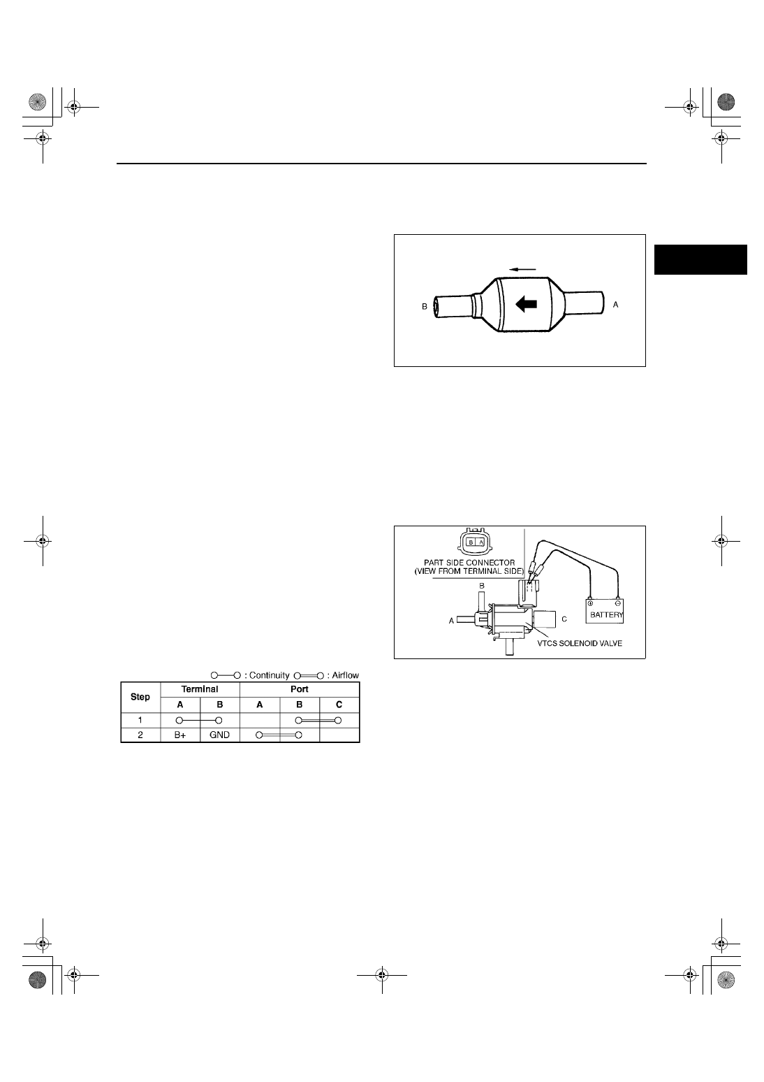
1. Remove the VTCS delay valve. (See 01–13A–10 VARIABLE TUMBLE CONTROL SYSTEM (VTCS) DELAY 

VALVE REMOVAL/INSTALLATION [ZM].)

2. Blow through port A and verify that the air flows from port B.

If not as specified, replace the VTCS delay valve.

3. Blow through port B and verify that the air does 

not flow from port A.

If not as specified, replace the VTCS delay 
valve.

End Of Sie

VARIABLE TUMBLE CONTROL SYSTEM (VTCS) SOLENOID VALVE INSPECTION [ZM]

A3U011318745W02

Simulation Test

1. Carry out the “VTCS Operation Inspection”. (See 01–03A–58 Variable Tumble Control System (VTCS) 

Inspection.)

If not as specified, perform the further inspection for the VTCS solenoid valve.

Airflow Inspection

Note

Perform the following test only as directed.

1. Remove the VTCS solenoid valve.
2. Inspect airflow each port under the following 

condition.

If as specified, replace the VTCS solenoid 
valve.

If as specified but the “VTCS Operation 
Inspection” is failed, inspect evaporative 
hoses for improper routing, kinks or leakage, 
and “Circuit Open/Short Inspection”.
— If there is an open or short circuit, repair 

or replace wiring harnesses.

— If the above open or short circuit is okay, 

replace VTCS solenoid valve.

X3U113WAA

Y3U113WA4

X3U113WAI

1712-1U-01G(01-13A).fm  11 ページ  2001年6月29日 金曜日 午前9時42分

INTAKE-AIR SYSTEM [ZM]

01–13A–12

Circuit Open/Short Inspection

1. Remove the PCM. (See 01–40A–7 PCM REMOVAL/INSTALLATION [ZM].)
2. Connect the SST (104 Pin Breakout Box) to the 

PCM as shown.

3. Tighten the connector attaching screw.

Tightening torque

7.9—10.7 N·m {80—110 kgf·cm, 69.5—95.4 

in·lbf}

4. Inspect for an open or short circuit in the following 

wiring harnesses by probing the applicable 
sensor and SST (104 Pin Breakout Box) terminals 
with ohmmeter leads.
Open circuit

Power circuit (VTCS solenoid valve connector 
terminal A and main relay connector terminal 
D through common connector)

Control circuit (VTCS solenoid valve 
connector terminal B and PCM connector 
terminal 19)

Short circuit

Power circuit (VTCS solenoid valve connector 
terminal A and main relay connector terminal 
D through common connector to GND)

Control circuit (VTCS solenoid valve connector terminal B and PCM connector terminal 19 to GND)

5. Reconnect the VTCS solenoid valve connector.
6. Reconnect the negative battery cable.

End Of Sie

ACCELERATOR CABLE REMOVAL/INSTALLATION [ZM]

A3U011341660W04

Note

Accelerator removal and installation on cruise control system–equipped vehicles is not possible.

1. Remove in the order indicated in the table.

2. Install in the reverse order of removal.

X3U113WAC

Z3U0113W998

1

Retainer

2

E-ring

3

Accelerator pedal
(See 01–13A–13 Accelerator Pedal Installation 
Note)

4

Return spring

X3U113WAD

1712-1U-01G(01-13A).fm  12 ページ  2001年6月29日 金曜日 午前9時42分

INTAKE-AIR SYSTEM [ZM]

01–13A–13

01–13A

Accelerator Pedal Installation Note

1. Set the accelerator pedal securely, taking care not to bend the accelerator cable.

End Of Sie

ACCELERATOR CABLE INSPECTION/ADJUSTMENT [ZM]

A3U011341660W05

1. Verify that the throttle valve is fully closed.
2. Pull the accelerator cable in A and B directions, and measure the free play.

If not as specified, adjust by turning locknuts C.

Free Play

1—3 mm {0.04—0.11 in}

Tightening torque

10—14 N·m {1.0—1.5 kgf·m, 8—10 ft·lbf}

End Of Sie

X3U113WAE

1712-1U-01G(01-13A).fm  13 ページ  2001年6月29日 金曜日 午前9時42分

INTAKE-AIR SYSTEM [FS]

01–13B–1

01–13B

01–13B INTAKE-AIR SYSTEM [FS]

INTAKE-AIR SYSTEM LOCATION INDEX 

[FS]  . . . . . . . . . . . . . . . . . . . . . . . . . . . .  01–13B–2

INTAKE-AIR SYSTEM FLOW DIAGRAM 

[FS]  . . . . . . . . . . . . . . . . . . . . . . . . . . . .  01–13B–4

VACUUM HOSE ROUTING DIAGRAM 

[FS]  . . . . . . . . . . . . . . . . . . . . . . . . . . . .  01–13B–5

INTAKE-AIR SYSTEM REMOVAL/INSTALLATION 

[FS]  . . . . . . . . . . . . . . . . . . . . . . . . . . . .  01–13B–6

Throttle Body Removal Note  . . . . . . . .  01–13B–7
Intake Manifold Removal Note . . . . . . .  01–13B–7
Dynamic Chamber Gasket Installation Note

. . . . . . . . . . . . . . . . . . . . . . . . . . . . . .  01–13B–7

Intake Manifold Gasket Installation Note01–13B–7
Throttle Body Installation Note . . . . . . .  01–13B–7
Accelerator Cable Installation Note . . .  01–13B–7

IDLE AIR CONTROL (IAC) VALVE REMOVAL/

INSTALLATION [FS]. . . . . . . . . . . . . . .  01–13B–8

IDLE AIR CONTROL (IAC) VALVE 

INSPECTION [FS] . . . . . . . . . . . . . . . . .  01–13B–8

Resistance Inspection  . . . . . . . . . . . . .  01–13B–8
Circuit Open/Short Inspection  . . . . . . .  01–13B–9

VACUUM CHAMBER CHECK VALVE REMOVAL/

INSTALLATION [FS]. . . . . . . . . . . . . . .  01–13B–9

VACUUM CHAMBER CHECK VALVE INSPECTION 

[FS]  . . . . . . . . . . . . . . . . . . . . . . . . . . . .  01–13B–9

VARIABLE INERTIA CHARGING SYSTEM (VICS) 

DIAGRAM [FS]  . . . . . . . . . . . . . . . . . . .  01–13B–10

VARIABLE INERTIA CHARGING SYSTEM (VICS) 

CHECK VALVE (ONE-WAY) REMOVAL/
INSTALLATION [FS]. . . . . . . . . . . . . . .  01–13B–10

VARIABLE INERTIA CHARGING SYSTEM (VICS) 

CHECK VALVE (ONE-WAY) INSPECTION 
[FS]  . . . . . . . . . . . . . . . . . . . . . . . . . . . .  01–13B–10

VARIABLE INERTIA CHARGING SYSTEM (VICS) 

SHUTTER VALVE ACTUATOR REMOVAL/
INSTALLATION [FS]. . . . . . . . . . . . . . .  01–13B–11

VARIABLE INERTIA CHARGING SYSTEM (VICS) 

SHUTTER VALVE ACTUATOR INSPECTION 
[FS] . . . . . . . . . . . . . . . . . . . . . . . . . . . . . 01–13B–11

Operating Inspection . . . . . . . . . . . . . . . 01–13B–11

VARIABLE INERTIA CHARGING SYSTEM (VICS) 

SOLENOID VALVE INSPECTION [FS] . 01–13B–12

Airflow Inspection  . . . . . . . . . . . . . . . . . 01–13B–12
Circuit Open/Short Inspection . . . . . . . . 01–13B–12

VARIABLE TUMBLE CONTROL SYSTEM (VTCS) 

DIAGRAM [FS] . . . . . . . . . . . . . . . . . . . . 01–13B–13

VARIABLE TUMBLE CONTROL SYSTEM (VTCS) 

SHUTTER VALVE ACTUATOR REMOVAL/
INSTALLATION [FS]  . . . . . . . . . . . . . . . 01–13B–13

VARIABLE TUMBLE CONTROL SYSTEM (VTCS) 

SHUTTER VALVE ACTUATOR INSPECTION 
[FS] . . . . . . . . . . . . . . . . . . . . . . . . . . . . . 01–13B–14

Operating Inspection . . . . . . . . . . . . . . . 01–13B–14

VARIABLE TUMBLE CONTROL SYSTEM (VTCS) 

DELAY VALVE REMOVAL/INSTALLATION 
[FS] . . . . . . . . . . . . . . . . . . . . . . . . . . . . . 01–13B–14

VARIABLE TUMBLE CONTROL SYSTEM (VTCS) 

DELAY VALVE INSPECTION [FS]  . . . . 01–13B–15

VARIABLE TUMBLE CONTROL SYSTEM (VTCS) 

SOLENOID VALVE INSPECTION [FS] . 01–13B–15

Simulation Test . . . . . . . . . . . . . . . . . . . 01–13B–15
Airflow Inspection  . . . . . . . . . . . . . . . . . 01–13B–15
Circuit Open/Short Inspection . . . . . . . . 01–13B–16

ACCELERATOR CABLE REMOVAL/

INSTALLATION [FS]  . . . . . . . . . . . . . . . 01–13B–16

Accelerator Pedal Installation Note . . . . 01–13B–17

ACCELERATOR CABLE INSPECTION 

[FS] . . . . . . . . . . . . . . . . . . . . . . . . . . . . . 01–13B–17

ACCELERATOR CABLE ADJUSTMENT 

[FS] . . . . . . . . . . . . . . . . . . . . . . . . . . . . . 01–13B–17

End of Toc

1712-1U-01G(01-13B).fm  1 ページ  2001年6月29日 金曜日 午前9時42分


Content   ..  137  138  139  140   ..