Mazda Protege 5. Manual - part 138


  Index      Mazda     Mazda Protege 5 - service repair manual 2002 year


Search            


Content   ..  136  137  138  139   ..


Mazda Protege 5. Manual - part 138


INTAKE-AIR SYSTEM [ZM]

01–13A–7

01–13A

IDLE AIR CONTROL (IAC) VALVE INSPECTION [ZM]

A3U011320661W04

Resistance Inspection

Note

Perform the following test only as directed.

1. Carry out the “Idle Air Control (IAC) Inspection”. (See 01–03A–57 Idle Air Control (IAC) Inspection.)

If not as specified, perform the further inspection for the IAC valve.

2. Disconnect the negative battery cable.
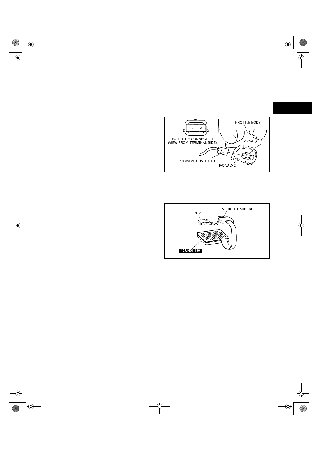
3. Disconnect the IAC valve connector.
4. Measure the resistance between the IAC valve 

terminals using an ohmmeter.

If not as specified, replace the IAC valve. 
(See 01–13A–6 IDLE AIR CONTROL (IAC) 
VALVE REMOVAL/INSTALLATION [ZM].)

If as specified, but PID value is failed, carry 
out the “Circuit Open/Short Inspection”.
— If there is an open or short circuit, repair 

or replace wiring harnesses.

— If the above open or short circuit is okay, 

replace IAC valve.

Resistance

7.7—9.3 ohms [23 

°°°°

C {73 

°°°°

F}]

Circuit Open/Short Inspection

1. Remove the PCM. (See 01–40A–7 PCM REMOVAL/INSTALLATION [ZM].)
2. Connect the SST (104 Pin Breakout Box) to the 

PCM as shown.

3. Tighten the connector attaching screw.

Tightening torque

7.9—10.7 N·m {80—110 kgf·cm, 69.5—95.4 

in·lbf}

4. Inspect for an open or short circuit in the following 

wiring harnesses by probing the applicable 
sensor and SST (104 Pin Breakout Box) terminals 
with ohmmeter leads.
Open circuit

Power circuit (IAC valve connector terminal A 
and PCM connector terminal 54)

GND circuit (IAC valve connector terminal B and PCM connector terminal 83)

Short circuit

Power circuit (IAC valve connector terminal A and PCM connector terminal 54 to GND)

GND circuit (IAC valve connector terminal B and PCM connector terminal 83 to GND)

5. Reconnect the IAC valve connector.
6. Reconnect the negative battery cable.

End Of Sie

Y3U113WA3

X3U113WAJ

1712-1U-01G(01-13A).fm  7 ページ  2001年6月29日 金曜日 午前9時42分

INTAKE-AIR SYSTEM [ZM]

01–13A–8

VARIABLE TUMBLE CONTROL SYSTEM (VTCS) DIAGRAM [ZM]

A3U011313012W02

End Of Sie

VARIABLE TUMBLE CONTROL SYSTEM (VTCS) CHECK VALVE (ONE-WAY) REMOVAL/INSTALLATION 
[ZM]

A3U011342913W01

1. Disconnect the negative battery cable.
2. Remove the air hose, throttle body and intake manifold. (See 01–13A–5 INTAKE-AIR SYSTEM REMOVAL/

INSTALLATION [ZM].)

3. Remove in the order indicated in the table.

4. Install in the reverse order of removal.

End Of Sie

Z3U0113W004

1

Vacuum hose

2

VTCS check valve (one-way)

X3U113WA5

1712-1U-01G(01-13A).fm  8 ページ  2001年6月29日 金曜日 午前9時42分

INTAKE-AIR SYSTEM [ZM]

01–13A–9

01–13A

VARIABLE TUMBLE CONTROL SYSTEM (VTCS) CHECK VALVE (ONE-WAY) INSPECTION [ZM]

A3U011342913W02

1. Remove the VTCS check valve (one-way). (See 01–13A–8 VARIABLE TUMBLE CONTROL SYSTEM (VTCS) 

CHECK VALVE (ONE-WAY) REMOVAL/INSTALLATION [ZM].)

2. Blow through port A and verify that the air flows from port B.

If not as specified, replace the VTCS check valve (one-way).

3. Blow through port B and verify that the air does 

not flow from port A.

If not as specified, replace the VTCS check 
valve (one-way).

End Of Sie

VARIABLE TUMBLE CONTROL SYSTEM (VTCS) SHUTTER VALVE ACTUATOR REMOVAL/INSTALLATION 
[ZM]

A3U011320153W03

1. Disconnect the negative battery cable.
2. Remove the air hose, throttle body and intake manifold. (See 01–13A–5 INTAKE-AIR SYSTEM REMOVAL/

INSTALLATION [ZM].)

3. Remove in the order indicated in the table.

4. Install in the reverse order of removal.

End Of Sie

Z3U0113W999

1

E-ring

2

Bolt

3

VTCS shutter valve actuator

Y3U113WA6

1712-1U-01G(01-13A).fm  9 ページ  2001年6月29日 金曜日 午前9時42分

INTAKE-AIR SYSTEM [ZM]

01–13A–10

VARIABLE TUMBLE CONTROL SYSTEM (VTCS) SHUTTER VALVE ACTUATOR INSPECTION [ZM]

A3U011320153W04

Operating Inspection

Note

Perform the following test only as directed.

1. Carry out the “VTCS Operation Inspection”. (See 01–03A–58 Variable Tumble Control System (VTCS) 

Inspection.)

If not as specified, perform the further inspection for the VTCS shutter valve actuator.

2. Disconnect the vacuum hose from the VTCS shutter valve actuator.
3. Connect a vacuum pump to the VTCS shutter valve actuator.
4. Apply pressure slowly and inspect the rod 

movement of the VTCS shutter valve actuator 
under the following condition.

If not as specified, replace the VTCS shutter 
valve actuator. (See 01–13A–9 VARIABLE 
TUMBLE CONTROL SYSTEM (VTCS) 
SHUTTER VALVE ACTUATOR REMOVAL/
INSTALLATION [ZM].)

If as specified, but “VTCS Operation 
Inspection” is failed, inspect the vacuum 
hoses for improper routing, kinks or leakage, 
and inspect the following:

5. Disconnect the vacuum pump to the VTCS 

shutter valve actuator.

6. Reconnect the vacuum hose from the VTCS 

shutter valve actuator.

End Of Sie

VARIABLE TUMBLE CONTROL SYSTEM (VTCS) DELAY VALVE REMOVAL/INSTALLATION [ZM]

A3U011318800W03

1. Disconnect the negative battery cable.
2. Remove in the order indicated in the table.

3. Install in the reverse order of removal.

End Of Sie

Pressure (kPa {mmHg, 

inHg})

Rod movement

Above –1.2 {–9.0, –0.35}

Not pulled

–3.6— –27.9

 {–28— –209, –1.1— –8.2

Start to move

Below –27.9 {–209, –8.2}

Fully pulled

X3U113WA8

1

Vacuum hose

2

VTCS delay valve

X3U113WA9

1712-1U-01G(01-13A).fm  10 ページ  2001年6月29日 金曜日 午前9時42分


Content   ..  136  137  138  139   ..