Mazda Protege 5. Manual - part 101


  Index      Mazda     Mazda Protege 5 - service repair manual 2002 year


Search            


Content   ..  99  100  101  102   ..


Mazda Protege 5. Manual - part 101


SYMPTOM TROUBLESHOOTING [ENGINE CONTROL SYSTEM (ZM)]

01–03A–57

01–03A

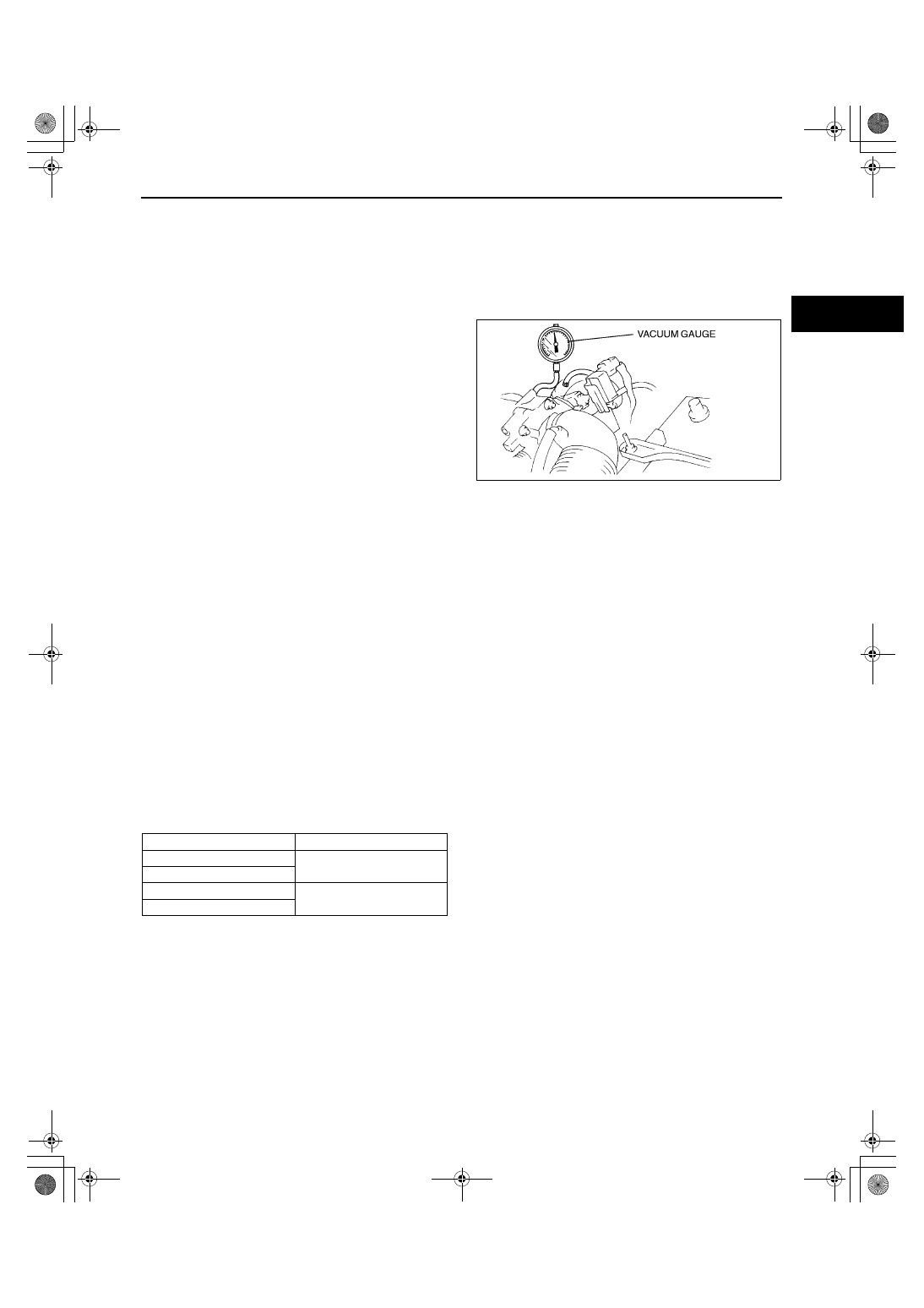
Intake Manifold Vacuum Inspection

1. Verify air intake hoses are installed properly.
2. Start the engine and run it at idle.
3. Measure the intake manifold vacuum using a vacuum gauge.

If not as specified, inspect the following:
— Air suction at throttle body, intake manifold and PCV valve installation points
— Fuel injector insulator
— Accelerator cable free play
— Engine compression (See 01–10A–8 

COMPRESSION INSPECTION [ZM].)

Specification

More than 60 kPa {450 mmHg, 18 inHg}

Note

Air suction can be located by engine speed 
change when lubricant is sprayed on the 
area where suction is occurring.

Idle Air Control (IAC) Inspection
Engine coolant temperature compensation inspection

1. Connect the WDS or equivalent to DLC-2.
2. Select the following PIDs.

ECT

RPM

3. Verify that the engine is in cold condition, then start the engine.
4. Verify that the engine speed decreases as the engine warms up.

If the engine speed does not decrease or decreases slowly, carry out the following:
— ECT sensor inspection
— IAC valve inspection

Load compensation inspection

1. Warm up the engine to normal operating temperature and run it at idle.
2. Connect the WDS or equivalent to DLC-2.
3. Select the following PID.

RPM

4. Turn the electrical loads on and verify that the engine speed is within the specification.

If not as specified, carry out the following:
— A/C switch inspection
— P/S pressure switch inspection
— IAC valve inspection

Engine speed (rpm)

*

: Neutral or P position

Note

Excludes temporary idle speed drop just after the loads are turned on.

X3U101WCW

Load condition

Idle-up speed (rpm)*

No load

650—750 (700

±

50)

Headlight switch is on.

P/S on

700—800 (750

±

50)

A/C on

1712-1U-01G(01-03A).fm  57 ページ  2001年6月29日 金曜日 午後4時45分

SYMPTOM TROUBLESHOOTING [ENGINE CONTROL SYSTEM (ZM)]

01–03A–58

Variable Tumble Control System (VTCS) Inspection

1. Connect the WDS or equivalent to the DLC-2.
2. Access ECT PID.
3. Verify ECT PID is 65 

°°°°

C {149 

°°°°

F} or less.

4. Start the engine.
5. Verify that the rod of tumble swirl control actuator is pulled.

If the rod is not pulled, inspect the following.
— VTCS shutter valve actuator
— VTCS delay valve
— VTCS chamber
— Vacuum hose
— Tumble swirl control solenoid valve
— Wiring harness and connectors (Main relay — VTCS solenoid valve — PCM terminal 19)

6. Access RPM PID.
7. Inspect the rod operation under the following 

condition.

If the rod operation is not as specified, inspect 
the following:
— Tumble swirl control actuator
— Vacuum delay valve
— Vacuum chamber
— Vacuum hose
— VTCS solenoid valve
— Wiring harness and connectors (Main 

relay — VTCS solenoid valve — PCM 
terminal 19)

Rod operation

Engine speed (RPM PID) 

(rpm)

Tumble swirl control 

actuator

3,000 or less

Operate

3,000 or more

Not operate

X3U101WEB

1712-1U-01G(01-03A).fm  58 ページ  2001年6月29日 金曜日 午後4時45分

SYMPTOM TROUBLESHOOTING [ENGINE CONTROL SYSTEM (ZM)]

01–03A–59

01–03A

Pressure Regulator Control Inspection

Warning

••••

Fuel line spills and leakage are dangerous. Fuel can ignite and cause serious injuries or death. 
Fuel can also irritate skin and eyes.

••••

To prevent this, always complete the “BEFORE REPAIR PROCEDURE”. (See 01–14–4 BEFORE 
REPAIR PROCEDURE.)

1. Disconnect the negative battery cable.
2. Connect a fuel pressure gauge between the fuel 

filter and fuel distributor.

3. Connect the negative battery cable.
4. Measure the fuel line pressure under the following 

conditions.

Specification

Inspection 1

1. Inspect the following.

ECT, IAT, TP PIDs.

Pressure regulator.

PRC solenoid valve.

Inspection 2

1. Inspect the following.

Loose or damage vacuum hose. (Pressure regulator—PRC solenoid valve—intake manifold)

PRC solenoid valve.

Condition

Fuel pressure (kPa {kgf/cm

2

, psi})

Idling

210—250 
{2.1—2.6, 

30—36}

210—250 

{2.1—2.6, 

30—36}

270—310 
{2.7—3.2, 

39—45}

During 100 
sec. of hot 
start

270—310 
{2.7—3.2, 

39—45}

After 100 sec. 
of hot start

210—250 
{2.1—2.6, 

30—36}

Judgment

Normal

Not Normal 

(Perform 

Inspection 1)

Not Normal 

(Perform 

Inspection 2)

X3U101WD7

1712-1U-01G(01-03A).fm  59 ページ  2001年6月29日 金曜日 午後4時45分

SYMPTOM TROUBLESHOOTING [ENGINE CONTROL SYSTEM (ZM)]

01–03A–60

Fuel Injector Operation Inspection

Spark Test

1. Disconnect the fuel pump relay connector.
2. Verify that each high-tension lead and connector is connected property.
3. Inspect the ignition system in the following procedure.

Warning

••••

High voltage in the ignition system can cause strong electrical shock which can result in serious 
injury. Avoid direct contact to the vehicle body during the following spark test.

End Of Sie

STEP

INSPECTION

ACTION

1

While cranking engine, inspect for fuel 
injector operation sound at each cylinder 
using a soundscope.

Is operation sound heard?

Yes

Fuel injector operation is okay.

No

All cylinders no heard:
Go to next step.
Some cylinders no heard:
Go to Step 3.

2

Carry out main relay operation inspection.

Is main relay operation normal?

Yes

Inspect following:
Fuel injector power system related wiring harness and 
connectors
PCM connectors
Fuel injector GND and related wiring harness and 
connectors

No

Repair or replace malfunctioning parts.

3

Change fuel injector connector of not 
operating fuel injector and operating fuel 
injector.

Is operation sound heard?

Yes

Go to next step.

No

Replace fuel injector.

4

Are wiring harness and connectors of not 
operating fuel injector okay? (Open or short)

Yes

Inspect PCM terminal voltage of fuel injector signal.

No

Repair or replace malfunctioning parts.

STEP

INSPECTION

ACTION

1

Remove high-tension lead from spark plug.

Hold high-tension lead with installed pliers 
5—10 mm {0.20—0.39 in} from GND.

Crank engine and verify there is a strong 
blue spark. (Inspect each cylinder.)

Yes

Ignition system is okay.

No

Some cylinders do not spark:
Go to next step.

All cylinders do not spark:
Go to Step 3.

2

Is high-tension lead resistance correct?

Yes

Inspect for cracks or damage of high-tension lead and 
ignition coil.

No

Replace high-tension lead.

3

Does PCM or ignition coil connector have 
poor connection?

Yes

Repair or replace connector.

No

Go to next step.

4

Is ignition coil winding resistance okay?

Yes

Go to next step.

No

Replace ignition coil.

5

Are following parts okay?
— CKP sensor and crankshaft pulley (also, 

inspect gap)

Specification
0.5—1.5 mm {0.020—0.059 in}

— PCM terminal 21/22 voltage

Specification
Approx. 1.5 V

Yes

Inspect for open or short in wiring harness and connector of 
CKP sensor.

No

Repair or replace malfunctioning parts.

1712-1U-01G(01-03A).fm  60 ページ  2001年6月29日 金曜日 午後4時45分


Content   ..  99  100  101  102   ..