Mazda Protege 5. Manual - part 82


  Index      Mazda     Mazda Protege 5 - service repair manual 2002 year


Search            


Content   ..  80  81  82  83   ..


Mazda Protege 5. Manual - part 82


ON-BOARD DIAGNOSTIC [ENGINE CONTROL SYSTEM (FS)]

01–02B–148

DTC P1570 [FS]

A3U010201083W12

Diagnostic procedure

DTC P1570

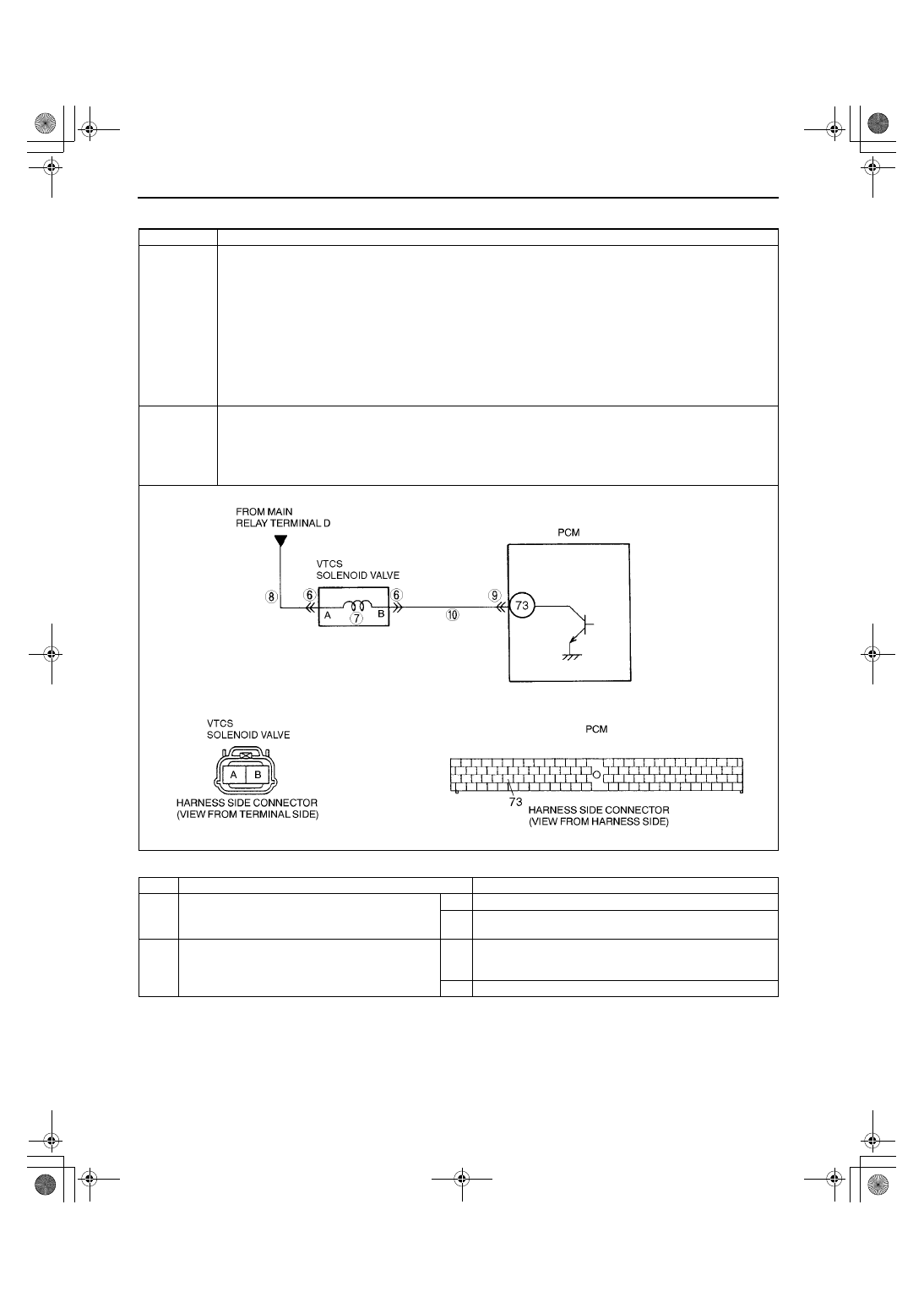
Variable tumble control system (VTCS) solenoid valve circuit high input

DETECTION 

CONDITION

PCM monitors input voltages from VTCS solenoid valve. If voltage at PCM 73 is high when the VTCS 
solenoid valve ON, PCM determines that VTCS solenoid valve malfunction.

MONITORING CONDITIONS

— Engine speed is below 3,250 rpm.
— Engine coolant temperature is below 65

°°°°

C {149 

°°°°

F}.

— Throttle valve opening angle is below 14% for ATX, 12.50% for MTX [at engine speed 2,500 rpm].

Diagnostic support note

This is a continuous monitor (CCM).

MIL illuminates if PCM detects the above the above malfunction condition in two consecutive drive cycles.

PENDING CODE is available if PCM detects the above malfunction condition during first drive cycle.

FREEZE FRAME DATA is available.

DTC is stored in PCM memory.

POSSIBLE 

CAUSE

Poor connection of connectors at PCM and/or VTCS solenoid valve

Short to power circuit in wiring between VTCS solenoid valve terminal B and PCM terminal 73

Open circuit in wiring between main relay terminal D and VTCS solenoid valve terminal A

Open circuit in wiring between VTCS solenoid valve terminal B and PCM terminal 73

VTCS solenoid valve malfunction

PCM malfunction

STEP

INSPECTION

ACTION

1

CHECK FREEZE FRAME DATA HAS BEEN 
RECORDED

Has FREEZE FRAME DATA been recorded?

Yes Go to next step.

No

Record FREEZE FRAME DATA on repair order, then go to 
next step.

2

VERIFY RELATED REPAIR INFORMATION 
AVAILABILITY

Check for related Service Bulletins availability.

Is any related repair information available?

Yes Perform repair or diagnosis according to available repair 

information.

If vehicle is not repaired, go to next step.

No

Go to next step.

1712-1U-01G(01-02B).fm  148 ページ  2001年6月29日 金曜日 午後3時24分

ON-BOARD DIAGNOSTIC [ENGINE CONTROL SYSTEM (FS)]

01–02B–149

01–02B

3

CLASSIFY INTERMITTENT CONCERN OR 
CONTINUOUS CONCERN

Clear DTC from PCM memory using WDS or 
equipment.

Start engine.

Drive vehicle under following conditions:
— Engine speed is below 3,250 rpm.
— Engine coolant temperature is below 65

°°°°

{149 

°°°°

F}.

— Throttle valve opening angle is below 14% 

for ATX, 12.50% for MTX [at engine speed 
2,500 rpm]
.

Is pending code of same DTC present?

Yes Go to next step.

No

Intermittent concern exists. Go to INTERMITTENT 
CONCERN TROUBLESHOOTING procedure.
(See 01–03B–4 INTERMITTENT CONCERN 
TROUBLESHOOTING [FS].)

4

CLASSIFY OPEN CIRCUIT OR SHORT TO 
GROUND MALFUNCTION

Disconnect VTCS solenoid valve tube that 
connects to intake manifold.

Connect vacuum pump to VTCS solenoid 
valve.

Apply vacuum and wait 5 seconds.

Is vacuum maintained?

Yes Go to Step 6.

No

Go to next step.

5

INSPECT PASSAGE CONTROL OF VTCS 
SOLENOID VALVE

Turn ignition key to OFF.

Disconnect VTCS solenoid valve connector.

Is vacuum maintained?

Yes Repair or replace harness between PCM terminal 73 and 

VTCS solenoid valve terminal B for short to ground, then go 
to Step 11.

No

Replace VTCS solenoid valve, then go to Step 11.

6

INSPECT POOR CONNECTION OF VTCS 
SOLENOID VALVE CONNECTOR

Turn ignition key to OFF.

Check for poor connection (damaged/pulled-
out pins, corrosion, etc.).

Is there malfunction?

Yes Repair or replace terminal, then go to Step 11.

No

Go to next step.

7

INSPECT VTCS SOLENOID VALVE

Measure resistance between VTCS solenoid 
valve terminals (part-side).

Is resistance within 22—26 ohms?

Yes Go to next step.

No

Replace VTCS solenoid valve, then go to Step 11.

8

INSPECT VTCS SOLENOID VALVE POWER 
SUPPLY CIRCUIT FOR OPEN CIRCUIT

Disconnect VTCS solenoid valve connector.

Turn ignition key to ON (Engine OFF).

Measure voltage between VTCS solenoid 
valve terminal A (harness-side) and body 
ground.

Is voltage B+?

Yes Go to next step.

No

Repair or replace harness for open, then go to Step 11.

9

INSPECT PCM CONNECTOR FOR POOR 
CONNECTION

Turn ignition key to OFF.

Disconnect PCM connector.

Check for poor connection at PCM terminal 73. 
(damaged/pulled-out pins, corrosion, etc.).

Is there malfunction?

Yes Repair terminal, then go to Step 11.

No

Go to next step.

10

INSPECT VTCS SOLENOID VALVE CONTROL 
CIRCUIT FOR SHORT TO POWER

Disconnect VTCS solenoid valve connector.

Connect breakout box with PCM disconnected.

Turn ignition key to ON (Engine OFF).

Measure voltage between breakout box 
terminal 73 and body ground.

Is voltage B+?

Yes Repair or replace harness for short to power circuit, then go 

to next step.

No

Go to next step.

STEP

INSPECTION

ACTION

1712-1U-01G(01-02B).fm  149 ページ  2001年6月29日 金曜日 午後3時24分

ON-BOARD DIAGNOSTIC [ENGINE CONTROL SYSTEM (FS)]

01–02B–150

End Of Sie

DTC P1631 [FS]

A3U010201083W13

11

VERIFY TROUBLESHOOTING OF DTC P1570 
COMPLETED

Make sure to reconnect all disconnected 
connectors.

Clear DTC from PCM memory using WDS or 
equipment.

Start engine.

Drive vehicle under following conditions:
— Engine speed is above 3,250 rpm.
— Engine coolant temperature is below 65

°°°°

{149 

°°°°

F}.

— Throttle valve opening angle is below 14% 

for ATX 12.50% for MTX [at engine speed 
2,500 rpm]
.

Is pending code of same DTC present?

Yes Replace PCM, then go to next step.

No

Go to next step.

12

VERIFY AFTER REPAIR PROCEDURE

Perform “After Repair Procedure”.
(See 01–02B–9 AFTER REPAIR 
PROCEDURE [FS].)

Is there any DTC present?

Yes Go to applicable DTC inspection.

(See 01–02B–15 DTC TABLE [FS].)

No

Troubleshooting completed.

STEP

INSPECTION

ACTION

DTC P1631

Generator output voltage signal no electricity

DETECTION 

CONDITION

PCM monitors input voltage from generator. If PCM detect generator output voltage below 8.5 V or 
generated current above 19.5 A for 5 seconds while engine running, PCM determines that charging 
system has malfunction.

POSSIBLE 

CAUSE

Open or short to ground circuit between generator terminal P and PCM terminal 30

Open or short to ground circuit between generator terminal D and PCM terminal 53

Drive belt is cut off or has come off

Generator malfunction
— Rectifier circuit malfunction
— Brush abrasion

PCM malfunction

1712-1U-01G(01-02B).fm  150 ページ  2001年6月29日 金曜日 午後3時24分

ON-BOARD DIAGNOSTIC [ENGINE CONTROL SYSTEM (FS)]

01–02B–151

01–02B

Diagnostic procedure

End Of Sie

STEP

INSPECTION

ACTION

1

VERIFY RELATED REPAIR INFORMATION 
AVAILABILITY

Check for related Service Bulletins availability.

Is any related repair information available? 

Yes Perform repair or diagnosis according to available repair 

information.

If vehicle is not repaired, go to next step.

No

Go to next step.

2

INSPECT DRIVE BELT CONDITION

Verify that drive belt auto tensioner indicator 
mark in not exceeding limit.
(See 01–10B–3 DRIVE BELT INSPECTION 
[FS].)

Is front drive belt okay?

Yes Go to next step.

No

Replace and/or adjust drive belt, then go to Step 9.

3

INSPECT PCM CONNECTOR FOR POOR 
CONNECTION

Turn ignition key to OFF.

Disconnect PCM connector.

Check for poor connection (damaged/pulled-
out terminals, corrosion, etc.).

Are there any malfunctions?

Yes Repair terminals, then go to Step 9.

No

Go to next step.

4

INSPECT GENERATOR CONNECTOR FOR 
POOR CONNECTION

Disconnect generator connector.

Check for poor connection (damaged/pulled-
out terminals, corrosion, etc.).

Are there any malfunctions?

Yes Repair or replace terminals, then go to Step 9.

No

Go to next step.

5

INSPECT GENERATOR CONTROL CIRCUIT 
FOR SHORT TO GROUND

Check for continuity between generator 
terminal D (harness-side) and body ground.

Is there continuity?

Yes Repair or replace harness for short to ground, then go to 

Step 9.

No

Go to next step.

6

INSPECT GENERATOR OUTPUT VOLTAGE 
MONITOR CIRCUIT FOR GROUND

Check continuity between generator terminal P 
(harness-side) and body ground.

Is there continuity?

Yes Repair or replace harness for short to ground, then go to 

Step 9.

No

Go to next step.

7

INSPECT GENERATOR CONTROL CIRCUIT 
FOR OPEN CIRCUIT

Connect breakout box with PCM disconnected.

Measure resistance between generator 
terminal D (harness-side) and breakout box 
terminal 53.

Is there continuity?

Yes Go to next step.

No

Repair or replace harness for open circuit, then go to Step 
9.

8

INSPECT GENERATOR OUTPUT VOLTAGE 
MONITOR CIRCUIT FOR OPEN CIRCUIT

Measure resistance between generator 
terminal P (harness-side) and breakout box 
terminal 30.

Is there continuity?

Yes Repair or replace generator, then go to next step.

No

Repair or replace harness for open, then go to next step.

9

VERIFY TROUBLESHOOTING OF DTC P1631 
COMPLETED

Make sure to reconnect all disconnected 
connectors.

Clear DTC from memory using WDS or 
equivalent.

Turn ignition switch to OFF, then start engine.

Is same DTC present?

Yes Replace PCM, then go to next step.

No

No concern is detected. Go to next step.

10

VERIFY AFTER REPAIR PROCEDURE

Perform “After Repair Procedure”.
(See 01–02B–9 AFTER REPAIR 
PROCEDURE [FS].)

Is there any DTC present?

Yes Go to applicable DTC inspection.

(See 01–02B–15 DTC TABLE [FS].)

No

Troubleshooting completed.

1712-1U-01G(01-02B).fm  151 ページ  2001年6月29日 金曜日 午後3時24分


Content   ..  80  81  82  83   ..