Mazda 5. Manual - part 41


  Index      Mazda     Mazda 5 - service repair manual


Search            


Content   ..  39  40  41  42   ..


Mazda 5. Manual - part 41


05–17–84

AUTOMATIC TRANSAXLE 

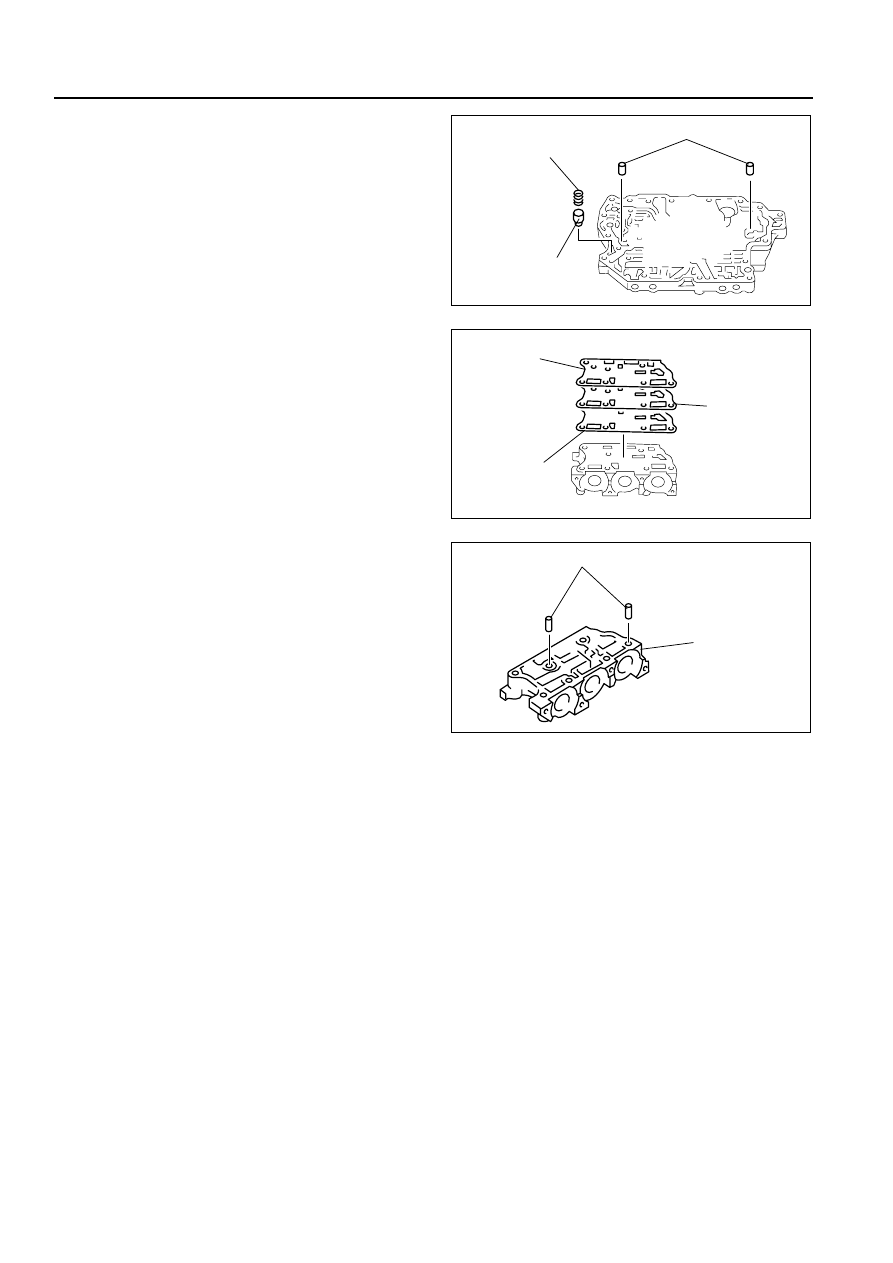
11. Remove the tubular pins, pressure modifier 

accumulator spring and pressure modifier 
accumulator from the main control valve body.

12. Remove the gasket D, separator plate and gasket 

C.

13. Remove the tubular pins.

Upper Control Valve Body Disassembly/Assembly

Caution

• Denting or scratching these precisely machined components will reduce the ability of the 

transaxle to shift properly. When handling these components or the valve body that contains 
them, be careful not to drop or hit them.

Note

• If a valve does not slide out under its own weight, place the valve body open-side down and tap on the 

valve body lightly with a plastic hammer.

1. Disassemble in the order indicated in the table.

Warning

• Using compressed air can cause dirt and other particles to fly out, causing injury to the eyes. 

Wear protective eye wear whenever using compressed air.

2. Clean all parts and holes using compressed air and apply ATF to them immediately before assembly.

TUBELAR PIN 

PRESSURE MODIFIER 
ACCUMULATOR SPRING

PRESSURE 
MODIFIER 
ACCUMULATOR

B3E0517A156

GASKET D

GASKET C

SEPARATOR 
PLATE

B3E0517A157

TUBULAR PIN

SOLENOID 
VALVE 
BODY

B3E0517A158

AUTOMATIC TRANSAXLE 

05–17–85

05

3. Assemble in the reverse order of disassembly.

Assembly procedure

1. Measure the spring free length.

• If not as specified, replace the springs.

2. Install the solenoid reducing valve, solenoid reducing valve spring and retainer.

1

Manual valve

2

Retainer

3

Low and reverse shift valve spring

4

Low and reverse shift valve

5

Retainer

6

Solenoid reducing valve spring

7

Solenoid reducing valve

7

5

4

3

1

2

6

SOLENOID 
REDUCING 
VALVE

LOW AND REVERSE 
SHIFT VALVE

MANUAL VALVE

SHIFT VALVE LOCATIONS

B3E0517A159

Item

Outer diameter

mm {in}

Free length

mm {in}

No. of coils

Wire diameter

mm {in}

Low and reverse shift 
valve spring

8.7 {0.343}

31.3 {1.232}

9.0

0.8 {0.031}

Solenoid reducing valve 
spring

8.7 {0.343}

44.2 {1.740}

16.0

1.1 {0.043}

05–17–86

AUTOMATIC TRANSAXLE 

3. Install the low and reverse shift valve, low and 

reverse shift valve spring and retainer.

4. Install the manual valve.

Main Control Valve Body Disassembly/Assembly

Caution

• Denting or scratching these precisely machined components will reduce the ability of the 

transaxle to shift properly. When handling these components or the valve body that contains them 
be careful not to drop or hit them.

Note

• If a valve does not slide out under its own weight, place the valve body open-side down and tap on the 

valve body lightly with a plastic hammer.

1. Disassemble in the order indicated in the table.

Warning

• Using compressed air can cause dirt and other particles to fly out, causing injury to the eyes. 

Wear protective eye wear whenever using compressed air.

2. Clean all parts and holes using compressed air and apply ATF to them immediately before assembly.

SOLENOID 
REDUCING 
VALVE

LOW AND REVERSE 
SHIFT VALVE

B3E0517A160

B3E0517A161

AUTOMATIC TRANSAXLE 

05–17–87

05

3. Assemble in the reverse order of disassembly.

1

Retainer

2

Stopper plug

3

Pressure regulator valve spring

4

Pressure regulator valve

5

Retainer

6

Solenoid shift valve spring

7

Solenoid shift valve

8

Retainer

9

Converter relief valve spring

10

Converter relief valve

11

Retainer

12

Torque converter clutch valve spring

13

Torque converter clutch valve

14

Retainer

9

8

7

5

4

3

1

2

10

19

18

17

15

16

14

13

11

12

6

SOLENOID 
SHIFT 
VALVE

3—4 SHIFT VALVE

BYPASS 
VALVE

SHIFT VALVE LOCATIONS

PRESSURE 
REGULATOR 
VALVE

CONVERTER 
RELIEF 
VALVE

TORQUE CONVERTER 
CLUTCH CONTROL VALVE

B3E0517A162


Content   ..  39  40  41  42   ..