Mazda 5. Manual - part 39


  Index      Mazda     Mazda 5 - service repair manual


Search            


Content   ..  37  38  39  40   ..


Mazda 5. Manual - part 39


05–17–76

AUTOMATIC TRANSAXLE 

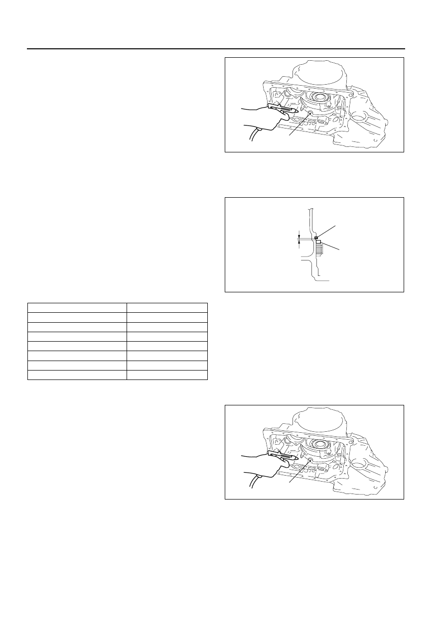
(3) Apply compressed air to the part indicated in 

the figure and let the low and reverse brake 
piston stroke three times.

Air pressure

98.1 kPa {1.0 kgf/cm

2

, 14 psi}

(4) Apply compressed air and operate the low 

and reverse brake piston. Read the value 
when the indicator of the dial gauge stops.

(5) Release the compressed air and read the dial 

gauge when the low and reverse brake piston 
is not operating.

(6) Calculate the low and reverse brake 

clearance according to the following formula:
Step (4) value—Step (5) value= low and reverse brake clearance.

(7) Measure the clearances at four locations (90

°

apart) by following the steps from (3) to (6). 
Verify that the average value is within the 
specification below:

Low and reverse brake clearance

2.20—2.50 mm {0.087—0.098 in}

• If not within the specification, remove the 

snap ring and measure its thickness.

(8) Add the thickness to the average value 

calculated in step (7), and select the snap ring 
whose range includes the value.

Snap ring seizes

(9) Install the selected snap ring and perform steps (2) to (7) again. Verify that the calculated value satisfies the 

clearance specification.

12. Inspect the low and reverse brake operation by 

applying compressed air as shown.

Air pressure

98.1 kPa {1.0 kgf/cm

2

, 14 psi}

End Of Sie

PARKING MECHANISM DISASSEMBLY/ASSEMBLY

B3E051721400A01

1. Disassemble in the order indicated in the table.

Range mm {in}

Snap ring sizes mm {in}

4.050—4.250 {0.159—0.167}

1.8 {0.071}

4.250—4.450 {0.167—0.175}

2.0 {0.079}

4.450—4.650 {0.175—0.183}

2.2 {0.087}

4.650—4.850 {0.183—0.190}

2.4 {0.094}

4.850—5.050 {0.190—0.199}

2.6 {0.102}

5.050—5.250 {0.199—0.207}

2.8 {0.110}

5.250—5.450 {0.207—0.215}

3.0 {0.118}

LOW AND REVERSE 
BRAKE FLUID PASSAGE

B3E0517A128

SNAP RING

CLEARANCE

RETAINING 
PLATE

B3E0517A134

LOW AND REVERSE 
BRAKE FLUID PASSAGE

B3E0517A128

AUTOMATIC TRANSAXLE 

05–17–77

05

2. Assemble in the reverse order of disassembly.

Assembly Procedure

1. Install the manual plate to the detent bracket 

component.

2. Install the parking assist lever component to the 

detent bracket component and the manual plate.

1

Actuator plate

2

Support actuator

3

Parking pawl shaft

4

Parking pawl

5

Pawl return spring

6

Manual shaft

7

Parking rod component

8

E-ring

9

Parking assist lever component

10

Manual plate

11

Detent bracket component

9

8

7

5

4

3

1

2

10

6

11

R

R

ATF

A

A

B3E0517A135

MANUAL PLATE

DETENT BRACKET

B3E0517A136

05–17–78

AUTOMATIC TRANSAXLE 

3. Install the E-ring.

4. Install the parking rod component.

End Of Sie

SECONDARY GEAR AND OUTPUT GEAR DISASSEMBLY/ASSEMBLY

B3E051719204A01

1. Disassemble in the order indicated in the table.
2. Assemble in the reverse order of disassembly.

E-RING

PARKING ASSIST 
LEVER COMPONENT

B3E0517A137

PARKING ROD 
COMPONENT

B3E0517A138

1

Ring

2

Bearing
(See 05–17–79 Bearing Disassembly Note.)

3

Secondary gear

4

Bearing
(See 05–17–79 Bearing Disassembly Note.)

5

Output gear

5

4

3

1

2

SST

SST

R

R

9.0—13.0 N·m {92—132 kgf·cm, 80—115 in·lbf}

B3E0517A139

AUTOMATIC TRANSAXLE 

05–17–79

05

Bearing Disassembly Note

1. Remove the bearing (secondary gear side) from 

the output gear using the SST.

2. Remove the bearing (output gear side) from the 

output gear using the SST.

Assembly Procedure

1. Install the output gear to the secondary gear 

using the SST.

2. Install the bearing (output gear side) to the output 

gear using the SST and suitable plate.

49 G030 160

PRESS

B3E0517A140

49 B017 206

49 G030 160

49 F401 366A

PRESS

B3E0517A141

49 0727 415

PRESS

B3E0517A142

49 V001 525

PRESS

SUITABLE PLATE

B3E0517A143


Content   ..  37  38  39  40   ..