Mazda 5. Manual - part 37
05–17–68
AUTOMATIC TRANSAXLE
Snap ring sizes
(9) Install the selected snap ring and perform steps (2) to (7) again. Verify that the calculated value satisfies the
clearance specification.
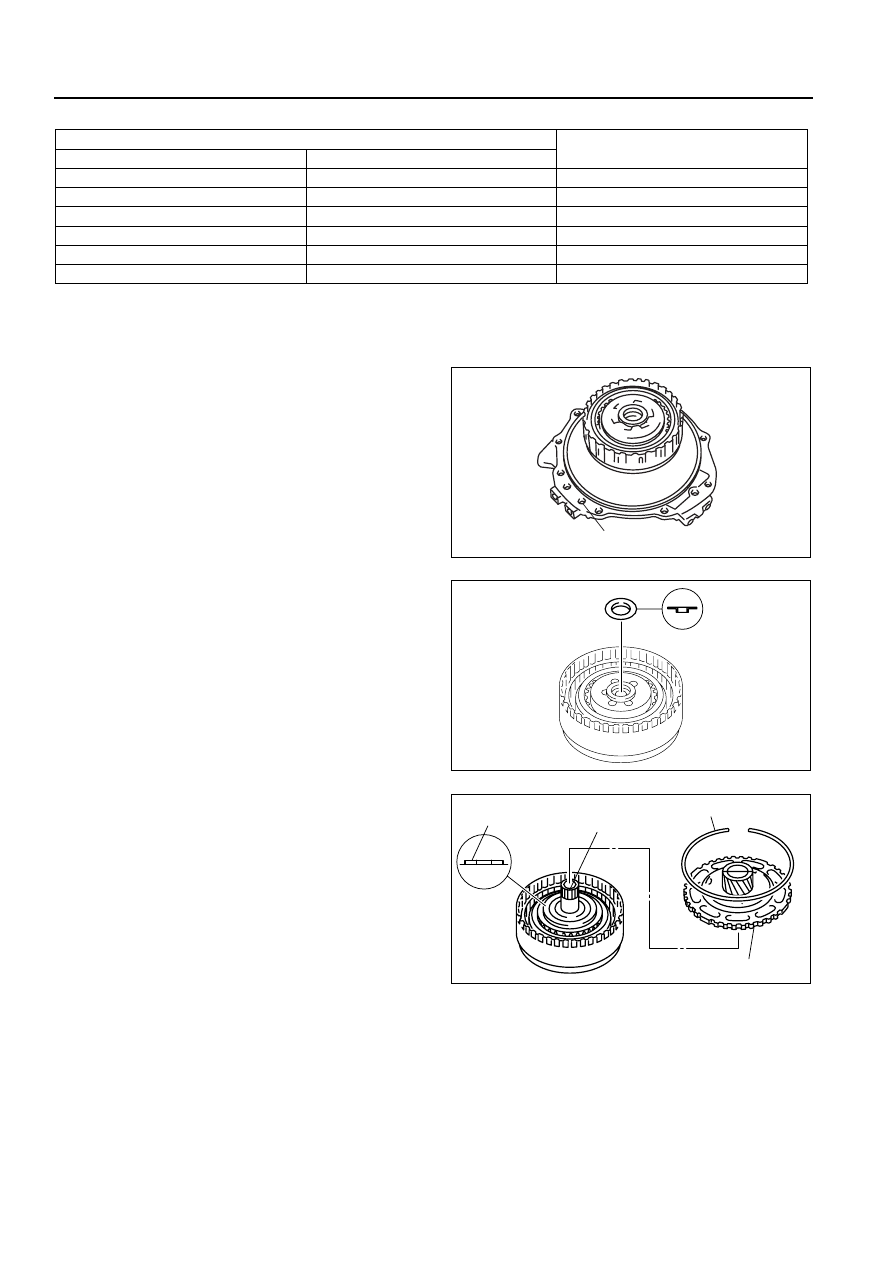
13. Inspect the 3–4 clutch operation.
(1) Install the 3–4 clutch drum to the end cover.
(2) Inspect the 3–4 clutch operation by applying
compressed air as shown.
Air pressure
392—441 kPa {4.0—4.5 kgf/cm
2
, 57—63 psi}
14. Install the 3–4 clutch component to the 2–4 brake
drum.
15. Apply petroleum jelly to the bearing, and secure it
onto the 3–4 clutch component.
16. Install the 3–4 clutch hub.
17. Apply petroleum jelly to the bearing, and secure it
onto the 3–4 clutch hub as shown in the figure.
18. Install the rear sun gear plate onto the 2–4 brake
drum.
19. Install the snap ring.
End Of Sie
FRONT INTERNAL GEAR ONE-WAY CLUTCH COMPONENT DISASSEMBLY/ASSEMBLY
B3E051719500A03
1. Perform the preinspection before disassembly.
(See 05–17–127 Front Internal Gear and One-Way Clutch Component.)
2. Disassemble in the order indicated in the table.
Range mm {in}
Snap ring sizes mm {in}
Drive plate part number:FN11 19 370
Drive plate part number:FNE1 19 370
2.250—2.450 {0.089—0.096}
2.350—2.550 {0.093—0.100}
1.2 {0.047}
2.450—2.650 {0.096—0.104}
2.550—2.750 {0.100—0.108}
1.4 {0.055}
2.650—2.850 {0.104—0.112}
2.750—2.950 {0.108—0.116}
1.6 {0.063}
2.850—3.050 {0.112—0.120}
2.950—3.150 {0.116—0.124}
1.8 {0.071}
3.050—3.250 {0.120—0.128}
3.150—3.350 {0.124—0.132}
2.0 {0.079}
3.250—3.450 {0.128—0.136}
3.350—3.550 {0.132—0.140}
2.2 {0.087}
3-4 CLUTCH FLUID PASSAGE
B3E0517A262
B3E0517A264
SNAP RING
3-4
CLUTCH HUB
BEARING
REAR SUN GEAR PLATE
B3E0517A265