Mazda 5. Manual - part 35


  Index      Mazda     Mazda 5 - service repair manual


Search            


Content   ..  33  34  35  36   ..


Mazda 5. Manual - part 35


05–17–60

AUTOMATIC TRANSAXLE 

Snap ring sizes

(9) Install the selected snap ring and perform steps (2) to (7) again. Verify that the calculated value satisfies the 

clearance specification.

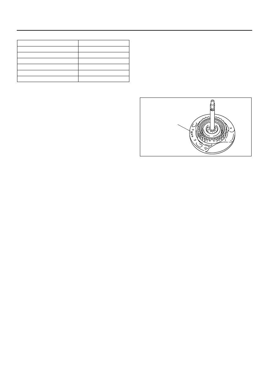
16. Inspect the forward clutch operation.

(1) Install the forward clutch drum and turbine 

shaft to the oil pump.

(2) Inspect the forward clutch operation by 

applying compressed air as shown.

Air pressure

392—441 kPa {4.0—4.5 kgf/cm

2

, 57—63 psi}

17. Install the forward clutch hub.

End Of Sie

CLUTCH COMPONENT DISASSEMBLY/ASSEMBLY

B3E051719500A02

1. Perform the preinspection before disassembly. (See 05–17–125 Clutch Component Preinspection.)
2. Disassemble in the order indicated in the table. 
3. Assemble in the reverse order of disassembly.

Range mm {in}

Snap ring sizes mm {in}

2.750—2.950 {0.108—0.116}

1.2 {0.047}

2.950—3.150 {0.116—0.124}

1.4 {0.055}

3.150—3.350 {0.124—0.132}

1.6 {0.063}

3.350—3.550 {0.132—0.140}

1.8 {0.071}

3.550—3.750 {0.140—0.148}

2.0 {0.079}

3.750—3.950 {0.148—0.155}

2.2 {0.087}

FORWARD CLUTCH 
FLUID PASSAGE

B3E0517A117

AUTOMATIC TRANSAXLE 

05–17–61

05

.

Snap Ring (3–4 clutch) Disassembly Note

1. Install the SST as shown.

Caution

• Depress the seal plate only enough to remove the snap ring. Overpressing will damage the seal 

plate assembly edges.

2. Compress the seal plate.

ATF

ATF

ATF

ATF

ATF

ATF

ATF

P

P

P

1

2

3

4

6

8

5

9

10

14

15

17

18

19

20

21

22

16

11

12

13

7

23

SST

SST

R

R

SELECTIVE

SELECTIVE

B3E0517A244

1

Snap ring

2

Rear sun gear plate

3

Bearing

4

3–4 clutch hub

5

Bearing

6

Snap ring

7

Retaining plate

8

Drive and driven plate

9

Snap ring
(See 05–17–61 Snap Ring (3–4 clutch) 
Disassembly Note.)

10

Seal plate

11

Spring and retainer component

12

3–4 clutch piston
(See 05–17–62 3–4 Clutch Piston Disassembly 
Note.)

13

3–4 clutch drum

14

Snap ring

15

Retaining plate

16

Drive and driven plate

17

Dish plate

18

Snap ring
(See 05–17–62 Snap Ring (Reverse clutch) 
Disassembly Note.)

19

Reverse return stopper

20

Piston return spring

21

Reverse piston
(See 05–17–62 Reverse Piston Disassembly Note.)

22

2–4 brake drum

23

Bearing

05–17–62

AUTOMATIC TRANSAXLE 

3. Remove the snap ring.
4. Remove the SST, then remove the seal plate and 

spring and retainer component.

3–4 Clutch Piston Disassembly Note

1. Set the 3–4 clutch drum onto the end cover.
2. Remove the 3–4 clutch piston from the 3–4 clutch 

drum by applying compressed air through the 
fluid passage.

Air pressure

392 kPa {4.0 kgf/cm

2

, 57 psi} max.

Snap Ring (Reverse clutch) Disassembly Note

1. Install the SSTs as shown.

Caution

• Depress the piston return spring only enough to remove the snap ring. Overpressing will damage 

the piston return spring assembly edges.

2. Compress the piston return spring.
3. Remove the snap ring.
4. Remove the SSTs, then remove the reverse 

return stopper and return spring.

Reverse Piston Disassembly Note

1. Set the 2–4 brake drum onto the end cover.

49 B019 012

SEAL PLATE

PRESS

B3E0517A245

CLUTCH PISTON

3-4 CLUTCH FLUID PASSAGE

B3E0517A246

49 G019 029

49 W019 002

49 G019 027

B3E0517A247

AUTOMATIC TRANSAXLE 

05–17–63

05

2. Remove the reverse piston from the 2–4 brake 

drum by applying compressed air through the 
fluid passage.

Air pressure

392 kPa {4.0 kgf/cm

2

, 57 psi} max.

Assembly Procedure

1. Measure the facing thickness in three places and calculate the average value.

Drive plate part number: FN11 19 370

Standard: 1.60 mm {0.063 in}
Minimum: 1.45 mm {0.057 in}

Drive plate part number: FNE1 19 370

Standard: 2.55 mm {0.100 in}
Minimum: 2.40 mm {0.094 in}

• If not within the specification, replace the drive plates.

2. Measure the free length of the spring and inspect 

for deformation.

Spring free length

Standard: 17.2 mm {0.677 in}
Minimum: 15.2 mm {0.598 in}

• If not within the specification, replace the 

spring and retainer.

3. Verify that there is airflow when applying 

compressed air through the fluid passage of 3–4 
clutch drum.

Air pressure

392 kPa {4.0 kgf/cm

2

, 57 psi} max.

4. Replace the 3–4 clutch drum if damaged or 

malfunctioning.

5. Verify that there is airflow when applying 

compressed air through the fluid passage of 2–4 
brake drum.

Air pressure

392 kPa {4.0 kgf/cm

2

, 57 psi} max.

6. Replace the 2–4 brake drum if damaged or 

malfunctioning.

REVERSE CLUTCH
FLUID PASSAGE

B3E0517A248

B3E0517A111

B3E0517A249

B3E0517A250


Content   ..  33  34  35  36   ..