Mazda 5. Manual - part 34


  Index      Mazda     Mazda 5 - service repair manual


Search            


Content   ..  32  33  34  35   ..


Mazda 5. Manual - part 34


05–17–56

AUTOMATIC TRANSAXLE 

10. Apply ATF to new seal rings and install them onto 

the oil pump cover.

Seal ring inner diameter

47.1 mm {1.854 in}

End Of Sie

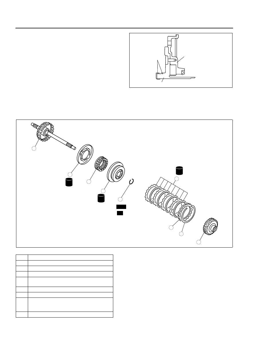
FORWARD CLUTCH DISASSEMBLY/ASSEMBLY

B3E051719500A01

1. Perform the preinspection before disassembly.

(See 05–17–124 Forward Clutch Preinspection.)

2. Disassemble in the order indicated in the table.
3. Assemble in the reverse order of disassembly.

Snap Ring Disassembly Note

1. Install the SST to the forward clutch.

Caution

OIL PUMP HOUSING

SEAL RING

OIL PUMP COVER

B3E0517A107

1

Forward clutch hub

2

Snap ring

3

Retaining plate

4

Drive and driven plate

5

Snap ring
(See 05–17–56 Snap Ring Disassembly Note.)

6

Seal plate

7

Springs and retainer component

8

Forward clutch piston
(See 05–17–57 Forward Clutch Piston 
Disassembly Note.)

9

Forward clutch drum and turbine shaft

ATF

ATF

ATF

SELECTIVE

SST

R

9

8

7

5

4

3

1

2

6

B3E0517A108

AUTOMATIC TRANSAXLE 

05–17–57

05

• Depress the seal plate only enough to remove the snap ring. Overpressing will damage the seal 

plate assembly edges.

2. Compress the seal plate.
3. Remove the snap ring.
4. Remove the SST, then remove the seal plate and 

spring and retainer component.

Forward Clutch Piston Disassembly Note

1. Set the forward clutch drum and turbine shaft onto the oil pump.
2. Remove the forward clutch piston by applying 

compressed air through the fluid passage.

Air pressure

392 kPa {4.0 kgf/cm

2

, 57 psi} max.

Assembly Procedure

1. Measure the facing thickness in three places, and calculate the average value.

Standard

1.60 mm {0.063 in}

Minimum

1.45 mm {0.057 in}

• If not within the specification, replace the drive plates.

2. Measure the spring free length.

Spring free length

Standard: 17.2 mm {0.677 in}
Minimum: 15.2 mm {0.598 in}

• If not within the specification, replace the 

spring and retainer component.

49 B019 012

SEAL PLATE

PRESS

B3E0517A109

FORWARD CLUTCH 
PISTON

FORWARD CLUTCH FLUID PASSAGE

B3E0517A110

B3E0517A111

05–17–58

AUTOMATIC TRANSAXLE 

3. Verify that there is airflow when applying 

compressed air through the fluid passage.

Air pressure

392 kPa {4.0 kgf/cm

2

, 57 psi} max.

4. Replace the forward clutch drum and turbine shaft 

if damaged or malfunctioning.

Caution

• Installing the forward clutch piston may 

damage its seal. Carefully install the 
forward clutch piston by pushing evenly 
around the circumference.

5. Apply ATF to the circumference of the forward 

clutch piston seal, and install the piston into the 
forward clutch drum and turbine shaft.

6. Install the spring and retainer component.

7. Apply ATF to the seal plate, and install it onto the 

forward clutch drum.

8. Install the SST to the forward clutch drum and 

turbine shaft as shown.

Caution

• Depress the seal plate only enough to 

remove the snap ring. Overpressing will 
damage the seal plate assembly edges.

9. Compress the seal plate.

10. Install the snap ring.
11. Remove the SST.
12. Install the drive and driven plates in the following 

order.
Driven—Drive—Driven—Drive—Driven—Drive—
Driven—Drive

13. Install the retaining plate.

B3E0517A112

FORWARD CLUTCH PISTON

FORWARD CLUTCH DRUM 
AND TURBINE SHAFT

B3E0517A113

SEAL PLATE

SPRING AND 
RETAINER 
COMPONENT

B3E0517A114

49 B019 012

SEAL PLATE

PRESS

B3E0517A109

AUTOMATIC TRANSAXLE 

05–17–59

05

14. Install the snap ring.
15. Measure the forward clutch clearance.

(1) Install the forward clutch in the oil pump, and 

set the dial gauge.

(2) Secure the forward clutch by lightly pressing 

down with a press or similar tool.

(3) Apply compressed air to the part indicated in 

the figure and let the forward clutch piston 
stroke three times.

Air pressure

392—441 kPa {4.0—4.5 kgf/cm

2

, 57—63 psi}

(4) Apply compressed air and operate the 

forward clutch piston. Read the value when 
the indicator of the dial gauge stops.

(5) Release the compressed air and read the dial 

gauge when the forward clutch piston is not 
operating.

(6) Calculate the forward clutch clearance 

according to the following formula:
Step (4) value— Step (5) value= Forward clutch clearance.

(7) Measure the clearances at four locations (90

° apart) by following the steps (3) to (6).

Verify that the average value is within the 
specification below:

Forward clutch clearance

1.50—1.80 mm {0.059—0.071 in}

• If not as specified, remove the snap ring 

and measure its thickness.

(8) Add the thickness to the average value 

calculated in step (7), and select the snap ring 
whose range includes the value.

SNAP RING

RETAINING PLATE

DRIVE AND 
DRIVEN PLATE

B3E0517A115

PRESS

DIAL GAUGE

RETAINING PLATE

B3E0517A116

FORWARD CLUTCH 
FLUID PASSAGE

B3E0517A117

SNAP RING

RETAINING PLATE

CLEARANCE

B3E0517A118


Content   ..  32  33  34  35   ..