Mazda 5. Manual - part 40
05–17–80
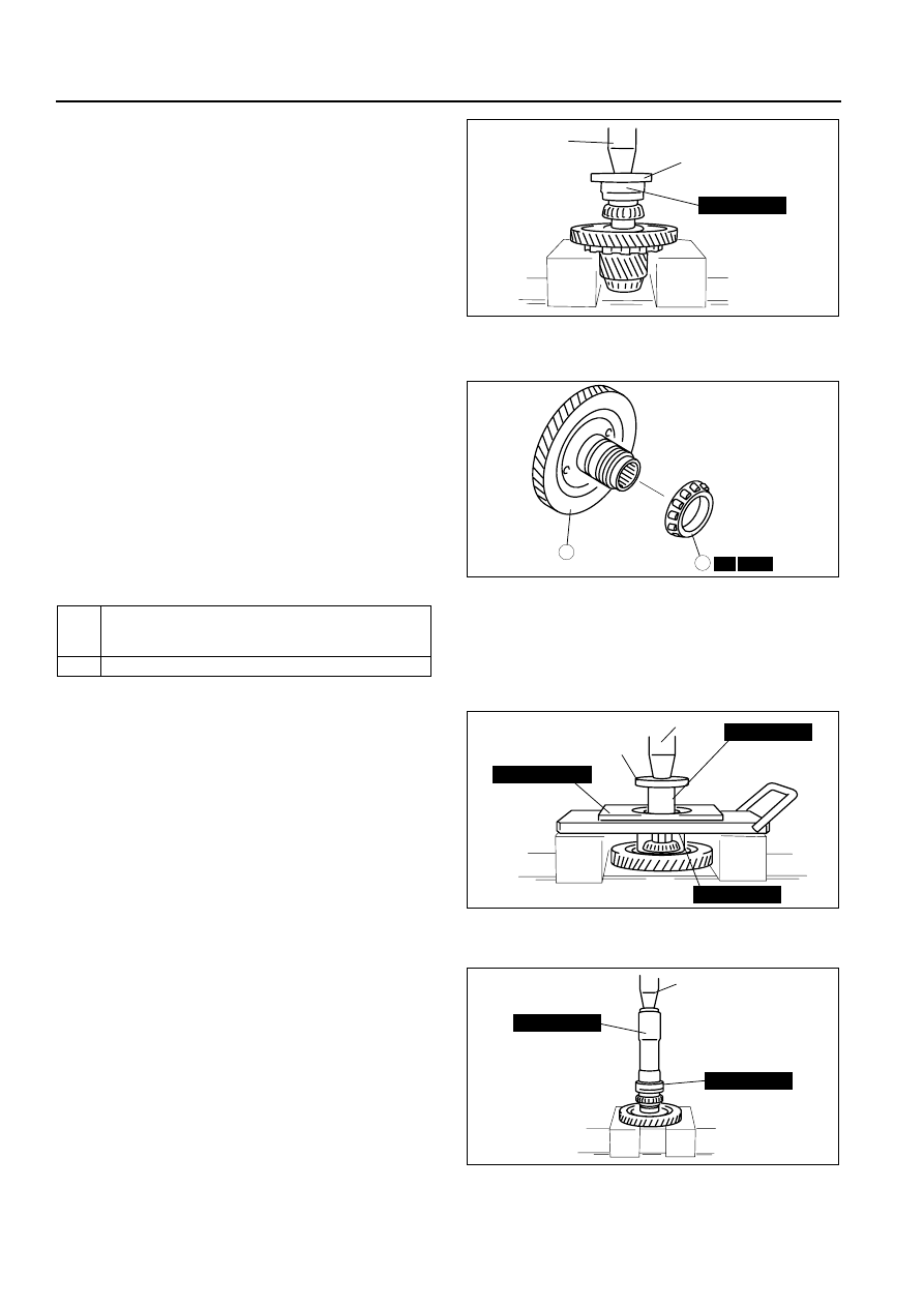
AUTOMATIC TRANSAXLE
3. Install the bearing (secondary gear side) to the
output gear using the SST and suitable plate.
End Of Sie
PRIMARY GEAR DISASSEMBLY/ASSEMBLY
B3E051719204A02
1. Disassemble in the order indicated in the table.
2. Assemble in the reverse order of disassembly.
Bearing Disassembly Note
• Remove the bearing from the primary gear using
the SSTs and suitable plate.
Bearing Assembly Note
• Install the bearing to the primary gear using the
SSTs.
End Of Sie
49 V001 525
PRESS
SUITABLE PLATE
B3E0517A144
SST
R
1
2
B3E0517A145
1
Bearing
(See 05–17–80 Bearing Disassembly Note.)
(See 05–17–80 Bearing Assembly Note.)
2
Primary gear
49 F026 102
49 T019 007
PRESS
SUITABLE PLATE
49 F401 366A
B3E0517A146
49 0727 415
49 UB71 525
PRESS
B3E0517A147