Mazda X-5. Manual - part 64
DYNAMIC STABILITY CONTROL
04–15–7
04–15
Operation
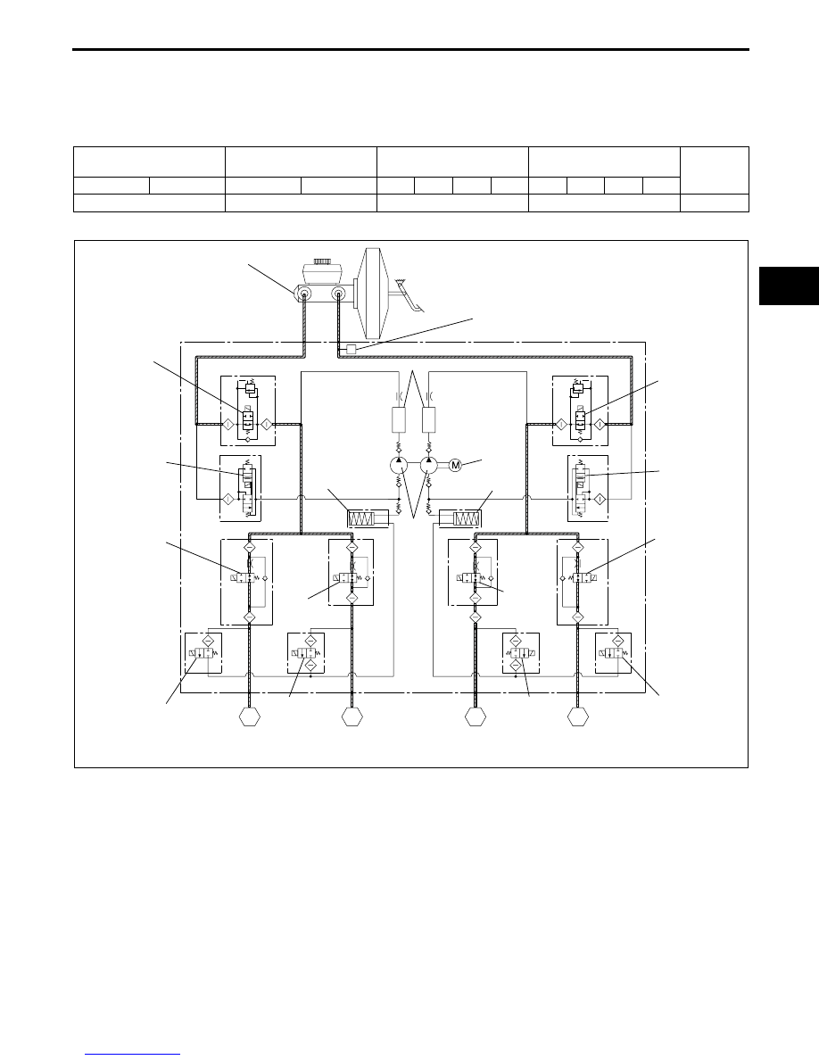
During normal braking
• During normal braking, the solenoid valves are not energized and all of them are off. When the brake pedal is
depressed, brake fluid pressure is transmitted from the master cylinder, through the traction switch and inlet
solenoid valves, and then to the caliper piston.
Solenoid valve operation table
Hydraulic circuit diagram
Traction control solenoid
valve
Stability control solenoid
valve
Inlet solenoid valve
Outlet solenoid valve
Pump
motor,
pump
LF—RR
RF—LR
LF—RR
RF—LR
LF
RF
LR
RR
LF
RF
LR
RR
OFF (open)
OFF (closed)
OFF (open)
OFF (closed)
Stopped
P
RF
LR
RR
LF
MASTER CYLINDER
TRACTION
CONTROL
SOLENOID
VALVE
TRACTION
CONTROL
SOLENOID
VALVE
BRAKE FLUID
PRESSURE SENSOR
STABILITY
CONTROL
SOLENOID
VALVE
STABILITY
CONTROL
SOLENOID
VALVE
INLET
SOLENOID
VALVE
INLET
SOLENOID
VALVE
INLET
SOLENOID
VALVE
INLET
SOLENOID
VALVE
OUTLET
SOLENOID
VALVE
OUTLET
SOLENOID
VALVE
OUTLET
SOLENOID
VALVE
OUTLET
SOLENOID
VALVE
DAMPER CHAMBER
RESERVOIR
RESERVOIR
PUMP
MOTOR
PUMP
PRESSURE
INCREASE
PRESSURE
INCREASE
PRESSURE
INCREASE
PRESSURE
INCREASE
E5U415ZS5005