Mazda X-5. Manual - part 63


  Index      Mazda     Mazda X-5 - service repair manual 2006 year


Search            


Content   ..  61  62  63  64   ..


Mazda X-5. Manual - part 63


DYNAMIC STABILITY CONTROL 

04–15–3

04–15

End Of Sie

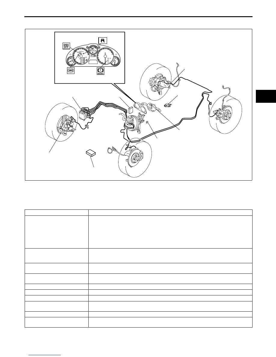
DYNAMIC STABILITY CONTROL (DSC) STRUCTURAL VIEW

E5U041500000N02

End Of Sie

DYNAMIC STABILITY CONTROL (DSC) CONSTRUCTION

E5U041500000N03

• The DSC system consists of the following parts. While each part has a regular function in other systems, only 

the function during DSC control is listed.

End Of Sie

BRAKE

BRAKE SYSTEM 
WARNING LIGHT

ABS WARNING 
LIGHT

REAR ABS WHEEL-
SPEED SENSOR

FRONT ABS WHEEL-
SPEED SENSOR

DSC OFF LIGHT

DSC INDICATOR LIGHT

STEERING ANGLE 
SENSOR

COMBINED 
SENSOR

DSC OFF SWITCH

DSC HU/CM 
(BUILT INTO BRAKE FLUID 
PRESSURE SENSOR)

PCM

TCM (AT)

E5U415ZS5002

Part name

Function

DSC HU/CM

• Makes calculations using input signals from each sensor, controls brake fluid pressure 

to each wheel, and actuates each function (ABS, EBD, TCS and DSC) of the DSC 
system.

• Outputs the torque reduction request signal, vehicle speed signal and DSC system 

warning control data via CAN lines.

• Controls the on-board diagnostic system and fail-safe function when there is a 

malfunction in the DSC system.

PCM

• Controls engine output based on signals from the DSC HU/CM.

• Transmits engine speed, tire and shift position data via CAN communication to the 

DSC HU/CM.

TCM (AT)

• Transmits gear/selector lever target position data via CAN communication to the DSC 

HU/CM.

DSC indicator light

• Informs the driver that the DSC is operating (vehicle sideslip occurring).

• Informs the driver that the TCS is operating (drive wheel is spinning).

DSC OFF switch

• Transmits driver intention to release DSC control to the DSC HU/CM.

DSC OFF light

• Informs driver that DSC control has been released due to DSC OFF switch operation.

Wheel speed sensor

• Detects the rotation condition of each wheel and transmits it to the DSC HU/CM.

Combined sensor

• Detects the lateral-G (vehicle speed increase) and the yaw rate (vehicle turning angle) 

of the vehicle and transmits them to the DSC HU/CM.

Brake fluid pressure sensor

• Detects the fluid pressure from the master cylinder and transmits it to the DSC HU/CM.

Steering angle sensor

• Transmits the steering angle and steering angle sensor condition via CAN lines to the 

DSC HU/CM.

DYNAMIC STABILITY CONTROL 

04–15–4

DYNAMIC STABILITY CONTROL (DSC) SYSTEM WIRING DIAGRAM

E5U041500000N04

End Of Sie

AE

AA

A

Y

AB

D

AI

B

I

O

N

P

M

F

E

L

G
H

A

X

W

J

C

E

C

F

A
B
D

IG SW

BATTERY

INSTRUMENT CLUSTER

CAN 
DRIVER

BRAKE SYSTEM 
WARNING LIGHT

ABS WARNING 
LIGHT

CAN 
DRIVER

PCM

TCM (ATX)

CAN 
DRIVER

CAN_H

CAN_L

CAN 
DRIVER

ABS 40A

ABS 30A

ENGINE 15A

DSC OFF LIGHT

DSC INDICATOR 
LIGHT

CAN_H

CAN_L

ABS WHEEL-
SPEED SENSOR

RF

LF

RR

LR

DSC HU/CM

IG 1

ROOM 15 A

COMBINED 
SENSOR

B

H

STEERING 
ANGLE 
SENSOR

E

F

CAN_H

CAN_L

BRAKE SWITCH

BRAKE 
LIGHT

DSC OFF SWITCH

DLC-2

E5U403ZW5002

DYNAMIC STABILITY CONTROL 

04–15–5

04–15

DSC HU/CM CONSTRUCTION

E5U041543750N01

• A high reliability, reduced size and weight DSC 

HU/CM, integrating both the DSC HU and the 
DSC CM, has been adopted.

End Of Sie

DSC HU PART FUNCTION

E5U041543750N02

• According to DSC CM signals, the DSC HU controls (on/off) each solenoid valve and the pump motor, adjusts 

fluid pressure in each caliper piston, and actuates each function (ABS, EBD (Electronic Brakeforce 
Distribution), TCS and DSC) of the DSC system.

End Of Sie

DSC HU PART CONSTRUCTION/OPERATION

E5U041543750N03

Construction
Function of main component parts

E5U415ZS5003

Part name

Function

Inlet solenoid valve

• Adjusts the fluid pressure in each brake system according to DSC HU/CM 

signals.

Outlet solenoid valve

• Adjusts the fluid pressure in each brake system according to DSC HU/CM 

signals.

Stability control solenoid valve

• Switches the brake hydraulic circuits during and according to normal braking, 

ABS and EBD control, TCS control and DSC control.

Traction control solenoid valve

• Switches the brake hydraulic circuits during and according to normal braking, 

ABS and EBD control, TCS control and DSC control.

Reservoir

• Temporarily stores brake fluid from the caliper piston to ensure smooth 

pressure reduction during ABS and EBD control, TCS control and DSC control.

Pump

• Returns the brake fluid stored in the reservoir to the master cylinder during ABS 

and DSC control.

• Increases brake fluid pressure and sends brake fluid to each caliper piston 

during TCS control and DSC control.

Pump motor

• Operates the pump according to DSC HU/CM signals.

DYNAMIC STABILITY CONTROL 

04–15–6

Hydraulic circuit diagram

P

RF

LR

RR

LF

MASTER CYLINDER

TRACTION 
CONTROL 
SOLENOID 
VALVE

TRACTION 
CONTROL 
SOLENOID 
VALVE

BRAKE FLUID 
PRESSURE SENSOR

STABILITY 
CONTROL 
SOLENOID 
VALVE

STABILITY 
CONTROL 
SOLENOID 
VALVE

INLET 
SOLENOID 
VALVE

INLET 
SOLENOID 
VALVE

INLET 
SOLENOID 
VALVE

INLET 
SOLENOID 
VALVE

OUTLET 
SOLENOID 
VALVE

OUTLET 
SOLENOID 
VALVE

OUTLET 
SOLENOID 
VALVE

OUTLET 
SOLENOID 
VALVE

DAMPER CHAMBER

RESERVOIR

RESERVOIR

PUMP 
MOTOR

PUMP

E5U415ZS5004


Content   ..  61  62  63  64   ..