Mazda X-5. Manual - part 62
ANTILOCK BRAKE SYSTEM
04–13–11
04–13
ABS WHEEL-SPEED SENSOR AND ABS SENSOR ROTOR CONSTRUCTION/OPERATION
E5U041343720N02
Construction
Front
• The front ABS wheel-speed sensor utilizes a
semi-conductor element that contains an active
drive circuit (MR element*). The front sensor is
installed on the front wheel hub.
• The front ABS sensor rotor utilizes a magnetic
encoder system that functions with magnetic
rubber, and is integrated into the wheel hub
component. Therefore, if there is any malfunction
of the front ABS sensor rotor, replace the wheel
hub component.
*
: A magneto-resistive force means that an exterior
magnetic field acts on the element, changing the
resistance of the element.
Caution
• When inspecting the ABS wheel-speed
sensor, do not use a tester to inspect
resistance. It is possible that the voltage
from the tester could damage the
semiconductor inside the ABS wheel-
speed sensor. Inspect using the PID data monitor of the WDS or equivalent.
Note
• Magnetic encoder: A plate that has positive and negative poles (marked out) in a continuous, alternating
line.
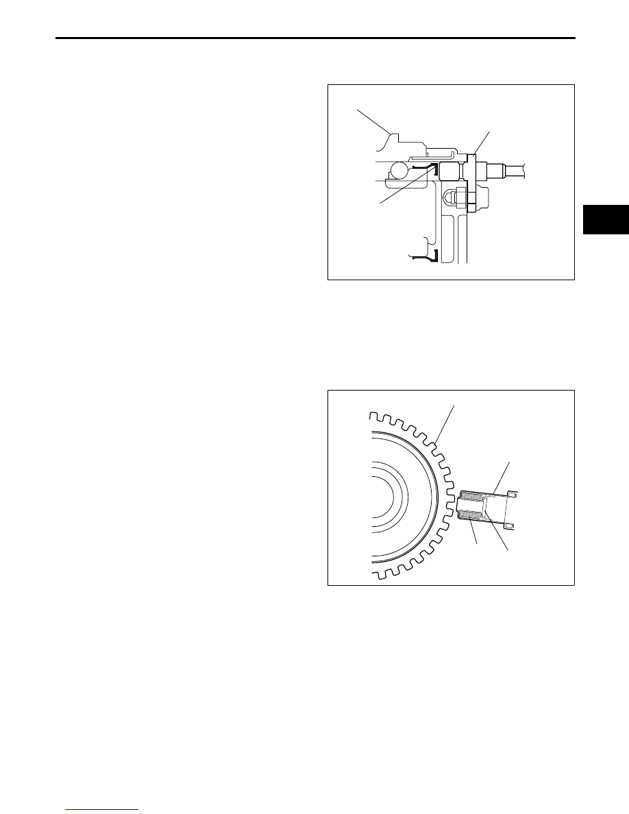
Rear
• The rear ABS wheel-speed sensor is installed on
the rear knuckle and the rear ABS sensor rotor is
integrated with the drive shaft. Therefore, if there
is any malfunction on the rear ABS sensor rotor,
replace the drive shaft.
FRONT ABS
SENSOR ROTOR
FRONT ABS WHEEL-
SPEED SENSOR
FRONT WHEEL HUB COMPONENT
E5U413ZS5010
REAR ABS SENSOR ROTOR
COIL
MAGNET
REAR ABS WHEEL-
SPEED SENSOR
DRIVE SHAFT
E5U413ZS5007