Range Rover Sport. Manual - part 79
Description
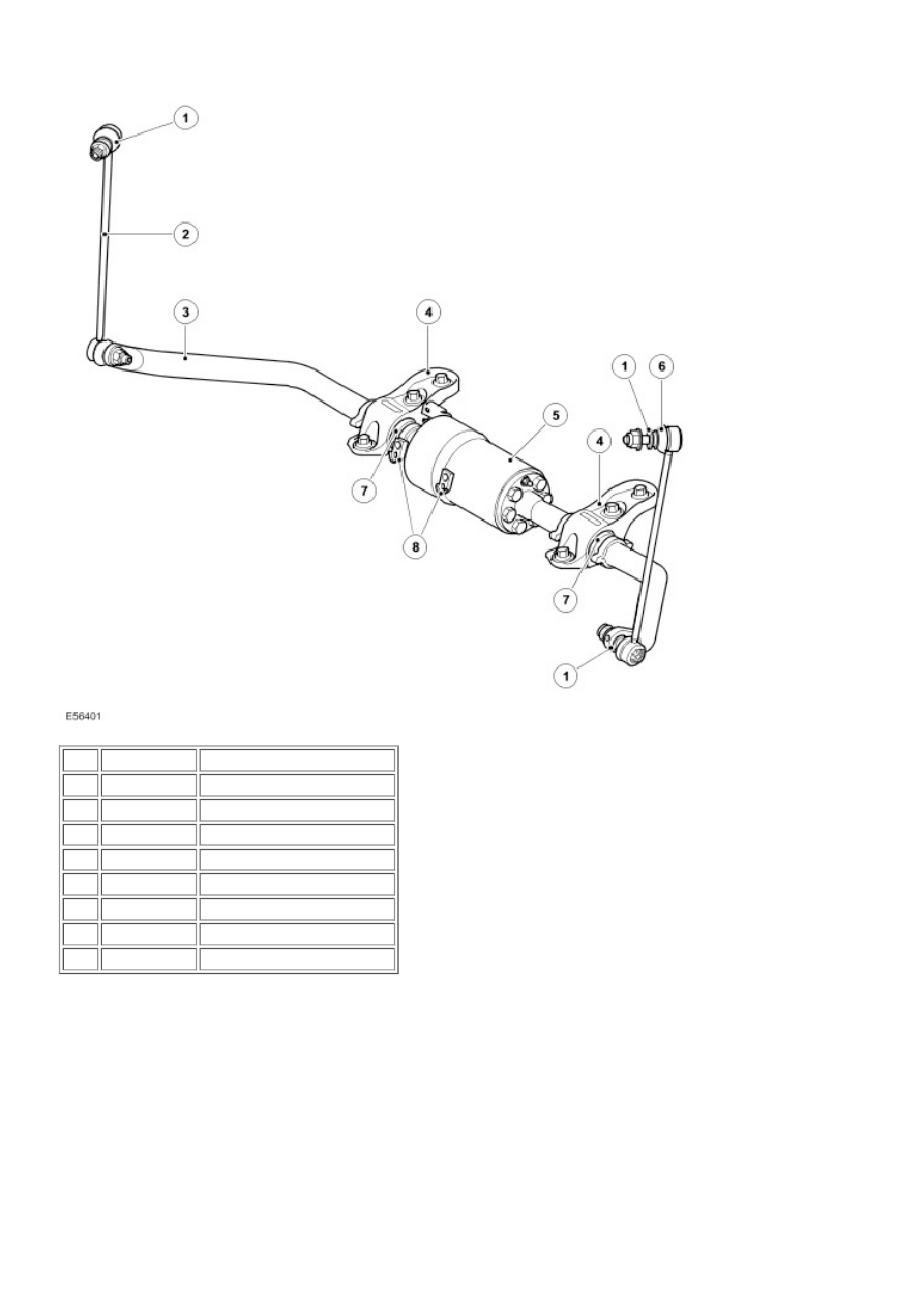
1
Hardened washer (4 off)
2
RH stabilizer link
3
Stabilizer bar
4
Chassis mounting brackets
5
Actuator
6
LH stabilizer link
7
Stabilizer bar mounting bush
8
Pipe fluid connections
Rear Actuator and Stabilizer Bar