Jeep XJ. Manual - part 488


  Index      Jeep     Jeep XJ - service repair manual 2001 year


Search            


Content   ..  486  487  488  489   ..


Jeep XJ. Manual - part 488


(3) Remove the screws that attach the liftgate trim

panel to the liftgate.

(4) Using a trim panel removal tool, detach the

push-in fasteners from the liftgate.

(5) Remove the trim panel from the liftgate.

INSTALLATION

(1) Position the trim panel on liftgate.
(2) Using new push-in fasteners, align the push-in

fasteners with the holes in the liftgate inner panel
and press the trim panel into place.

(3) Install the screws to attach the liftgate trim

panel to the liftgate.

(4) Install the screws attaching the assist handle

to the liftgate.

(5) Press the trim plugs into the liftgate assist

handle.

LIFTGATE

REMOVAL

WARNING: DO NOT DISCONNECT SUPPORT ROD
CYLINDERS WITH LIFTGATE CLOSED. SUPPORT
ROD PISTONS ARE OPERATED BY HIGH PRES-
SURE GAS. THIS COULD CAUSE DAMAGE AND/OR
PERSONAL INJURY IF THEY ARE REMOVED WHILE
PISTONS ARE COMPRESSED.

(1) Remove

center

high

mounted

stop

lamp

(CHMSL).

(2) Open and support liftgate.
(3) Remove liftgate trim panel.
(4) Disconnect and plug backlite washer fluid sup-

ply line.

(5) Remove screws that attach rear wiper and lift-

gate power lock wire harness connectors to liftgate
and disconnect connectors.

(6) Using

access

hole

created

by

removal

of

CHMSL, route backlite washer fluid supply line and
rear wiper and liftgate power lock wire harness/
grommets through access hole and separate from lift-
gate.

(7) Remove retainer clips that secure support rods

to ball studs.

(8) Remove support rods from ball studs.
(9) Remove bolts attaching hinges to liftgate.
(10) Remove liftgate from vehicle.

INSTALLATION

(1) Position and support liftgate at opening in body

and install bolts attaching hinges to liftgate. Tighten
bolts to 26 N·m (19 ft. lbs.) torque.

(2) Connect liftgate support rods to ball studs and

install retainer clips.

(3) Route backlite washer fluid supply line and

rear wiper and liftgate power lock wire harnesses/
grommets through access hole.

(4) Connect connectors and install screws that

attach rear wiper and liftgate power lock wire har-
ness connectors to liftgate

(5) Unplug and connect backlite washer fluid sup-

ply line.

(6) Install liftgate trim panel.
(7) Remove supports and close liftgate.
(8) Install (CHMSL).

LIFTGATE HINGE

REMOVAL

It is not necessary to remove the liftgate to replace

one or both hinges.

(1) Open and support the liftgate.
(2) Remove the liftgate opening upper trim.
(3) Remove the bolts attaching the hinge to the

header panel (Fig. 88).

(4) Remove the bolts attaching the hinge to the

liftgate.

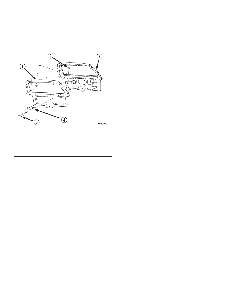
Fig. 87 Liftgate Trim Panel

1 – TRIM PANEL
2 – PUSH NUT
3 – LIFTGATE
4 – ASSIST HANDLE
5 – PLUG

23 - 62

BODY

XJ

REMOVAL AND INSTALLATION (Continued)

INSTALLATION

(1) Position the hinge on the liftgate.
(2) Install the bolts attaching the hinge to the lift-

gate. Tighten to 26 N·m (19 ft. lbs.) torque.

(3) Install the bolts attaching the hinge to the

header panel. Tighten to 26 N·m (19 ft. lbs.) torque.

(4) Install the liftgate opening upper trim.
(5) Remove the support and close the liftgate.

LIFTGATE SUPPORT ROD CYLINDER

REMOVAL

WARNING: DO NOT REMOVE A SUPPORT ROD
CYLINDER WITH THE LIFTGATE CLOSED. EACH
SUPPORT ROD PISTON IS OPERATED BY HIGH
PRESSURE GAS. IT CAN CAUSE DAMAGE AND/OR
PERSONAL INJURY IF IT IS REMOVED WITH THE
PISTON COMPRESSED. DO NOT ATTEMPT TO DIS-
ASSEMBLE OR REPAIR A SUPPORT ROD CYLIN-
DER.

(1) Open the liftgate.
(2) Support the liftgate in the open position.
(3) Remove the clip attaching the support rod to

the ball stud.

(4) Disconnect the support rod from the ball stud.
(5) Remove the bolts attaching the support rod to

the liftgate (Fig. 89).

(6) Separate the support rod from the liftgate.

INSTALLATION

(1) Position the support rod on the liftgate.

(2) Install the bolts attaching the support rod to

the liftgate.

(3) Connect the support rod to the ball stud.
(4) Secure the support rod to the ball stud with

the retainer clip.

(5) Remove the support from the liftgate.

LIFTGATE SUPPORT ROD BALL STUD

REMOVAL

(1) Open the liftgate.
(2) Support the liftgate in the open position.
(3) Remove the retainer clip attaching the support

rod to the ball stud.

(4) Disconnect the support rod from the ball stud.
(5) Remove the ball stud.

INSTALLATION

(1) Install the replacement ball stud.
(2) Connect the support rod to the ball stud.
(3) Secure the support rod to the ball stud with

the clip.

(4) Remove the support from the liftgate.

LIFTGATE OUTSIDE HANDLE

REMOVAL

(1) Remove liftgate trim panel.
(2) Disconnect liftgate actuator linkages.
(3) Disconnect liftgate outside handle to latch rod.
(4) Remove nut attaching outside handle to liftgate

(Fig. 90).

(5) Separate outside handle from liftgate.
(6) If necessary, remove lock cylinder (Fig. 91).

Fig. 88 Liftgate Hinge

1 – LIFTGATE HINGE
2 – LIFTGATE
3 – HEADER PANEL
4 – HEADER PANEL

Fig. 89 Liftgate Support Rod

1 – LIFTGATE
2 – SUPPORT ROD CYLINDER
3 – WASHER
4 – BALL STUD

XJ

BODY

23 - 63

REMOVAL AND INSTALLATION (Continued)

INSTALLATION

(1) If necessary, install lock cylinder.
(2) Position outside handle on liftgate.
(3) Install nut attaching outside handle to liftgate.
(4) Connect liftgate outside handle to latch rod.
(5) Connect liftgate actuator linkages.
(6) Install liftgate trim panel.

LIFTGATE LOCK CYLINDER

For service procedures, refer to the Liftgate Out-

side Handle Removal/Installation procedures.

LIFTGATE LATCH

REMOVAL

(1) Raise liftgate.
(2) Remove liftgate trim panel.
(3) Remove screws attaching latch to liftgate (Fig.

92).

(4) Disconnect rod from latch.
(5) Disconnect power lock connector from handle, if

equipped.

(6) Remove latch from liftgate.

INSTALLATION

(1) Position latch in liftgate.
(2) Connect power lock connector to handle, if

equipped.

(3) Connect latch rod.
(4) Install

screws

attaching

latch

to

liftgate.

Tighten screws to 13 N·m (9 ft. lbs.) torque.

(5) Install liftgate trim panel.

LIFTGATE LATCH STRIKER

REMOVAL

(1) From underside of vehicle, remove nuts attach-

ing striker to floor pan (Fig. 93).

(2) Separate striker from vehicle.

INSTALLATION

(1) Position striker on vehicle.
(2) Install nuts. Tighten nuts to 54 N·m (40 ft.

lbs.) torque.

Fig. 90 Liftgate Outside Handle

1 – POWER ACTUATOR
2 – LIFTGATE LOCK
3 – OUTSIDE HANDLE
4 – OUTSIDE HANDLE TO LATCH ROD
5 – LIFTGATE LATCH
6 – ACTUATOR TO LIFTGATE LOCK ROD

Fig. 91 Liftgate Lock Cylinder

1 – CLIP
2 – OUTSIDE HANDLE
3 – LOCK CYLINDER

Fig. 92 Liftgate Latch

1 – POWER ACTUATOR
2 – LIFTGATE LOCK
3 – OUTSIDE HANDLE
4 – OUTSIDE HANDLE TO LATCH ROD
5 – LIFTGATE LATCH
6 – ACTUATOR TO LIFTGATE LOCK ROD

23 - 64

BODY

XJ

REMOVAL AND INSTALLATION (Continued)

LIFTGATE WEATHERSTRIP

REMOVAL

(1) Pull the seal away from the flange around the

perimeter of liftgate opening and remove it.

(2) Clean the flange as necessary.

INSTALLATION

(1) Position weatherstrip seal in the opening with

the left end of the seal at the opening centerline.
Install the seal in a clockwise direction.

(2) Move to the left and mate the seal with the

bottom-left flange (Fig. 94).

(3) Move upward and mate the seal with the left-

side flange.

(4) Move to the right and mate the seal with the

top-left roof flange.

(5) Seat the installed part of the seal with a roller.

Move the roller from the left-bottom end of seal to
the top-left half of the seal.

(6) Move to the right and mate the seal with the

top-right roof flange.

(7) Move downward and mate the seal with the

right-side flange.

(8) Move to the left and mate the seal with the

bottom-right flange.

(9) Center and butt seal the ends together at the

centerline.

(10) Seat the remaining part of the seal with a

roller. Move the roller the from top-left half of the
seal to the right-bottom end of the seal.

ADJUSTMENTS

HOOD

The hood bolt holes are elongated for fore and aft

and side-to-side adjustment.

(1) If hood is low to the cowl panel, insert shims

between the hinge and hood at the rear hinge bolts.

(2) Adjust the hood bumper (Fig. 95) in or out to

provide proper hood-to-fender height alignment.

(3) Adjust the hood strikers (Fig. 96) with shims

as necessary. Tighten the screws to 22 N·m (16 ft-lbs)
torque after adjustment.

(4) Align each latch and striker so that the striker

enters latch squarely.

DOOR

IN AND OUT—MINOR ADJUSTMENT

(1) Loosen the latch striker.
(2) Tap the latch striker inward if the door charac-

ter line is outboard of the body character line or tap
the latch striker outward if the door character line is
inboard of the body character line.

(3) Inspect alignment. If correct, tighten striker

with 28 N·m (20 ft. lbs.) torque.

Fig. 93 Liftgagte Striker

1 – OVERSLAM BUMPER
2 – STRIKER PLATE
3 – STRIKER
4 – SHIM

Fig. 94 Liftgate Weatherstrip Installation

1 – LIFTGATE OPENING
2 – WEATHERSTRIP SEAL

XJ

BODY

23 - 65

REMOVAL AND INSTALLATION (Continued)


Content   ..  486  487  488  489   ..