Jeep XJ. Manual - part 487


  Index      Jeep     Jeep XJ - service repair manual 2001 year


Search            


Content   ..  485  486  487  488   ..


Jeep XJ. Manual - part 487


(3) Open the console lid.
(4) Remove the screws attaching the console to the

floor and mounting bracket (Fig. 77).

(5) Disconnect the wire harness connector.
(6) Separate the console from the floor.

INSTALLATION

(1) Position the console on the floor.
(2) Attach the air duct to the air outlet duct.
(3) Connect the wire harness connectors.
(4) Install the screws attaching the console to the

mounting bracket.

(5) Install the shift indicator bezels (or cover

plate).

(6) Install the shift lever handle/knob.

FRONT CARPET/MAT

REMOVAL

(1) Remove the door sill inner scuff plates.
(2) Remove the front and rear seats (as applica-

ble).

(3) Remove floor console.
(4) As necessary, remove the trim panels and

moldings.

(5) Remove all other interfering components.
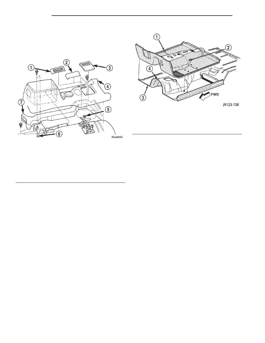
(6) Remove the carpet and mat from the floor

panel (Fig. 78).

INSTALLATION

(1) Position the carpet and mat on the floor panel.

(2) Install all the components that were removed

to facilitate carpet/mat removal.

(3) Install the trim panels and moldings.
(4) Install the door sill inner scuff plates.
(5) Install floor console.
(6) Install the front and rear seats (as applicable).

REAR CARPET/MAT

REMOVAL

(1) Remove the liftgate latch striker and scuff

plate.

(2) Drill-out the retaining rivet heads and remove

the cargo tie-down footman loops from the carpet.

(3) As necessary, remove the trim panels and

moldings.

(4) Remove the all other interfering components.
(5) Remove the carpet and mat from the floor

panel.

(6) If necessary, remove the insulation from the

wheelhouse (Fig. 79).

INSTALLATION

(1) If removed, install the insulation on the wheel-

houses.

(2) Position the mat on the floor panel.
(3) Position the carpet on the mat.
(4) Install all the components that were removed

to facilitate carpet and mat removal.

(5) Install the trim panels and moldings.
(6) Install the cargo tie-down footman loops on the

carpet with replacement rivets.

(7) Install the liftgate scuff plate and latch striker.

Fig. 77 Floor Console

1 – TRANSFER CASE SHIFT BEZEL
2 – COVER
3 – TRANS SHIFT BEZEL
4 – FLOOR CONSOLE
5 – WASHER (2WD)
6 – BRACKET
7 – DUCT

Fig. 78 Front Carpet and Mat

1 – CARPET AND MAT
2 – POWER SEAT WIRE HARNESS SLOT
3 – FLOOR PANEL
4 – SEAT FRAME STUD

23 - 58

BODY

XJ

REMOVAL AND INSTALLATION (Continued)

REARVIEW MIRROR

REMOVAL

(1) Loosen the mirror base setscrew (Fig. 80).
(2) Slide the mirror base upward and off the

bracket.

INSTALLATION

(1) Position the mirror base at the bracket and

slide it downward onto the support bracket.

(2) Tighten setscrew to1 N·m (9 in. lbs.) torque.

REARVIEW MIRROR SUPPORT BRACKET

INSTALLATION

(1) Mark the position for the mirror bracket on the

outside of the windshield glass with a wax pencil.

(2) Clean the bracket contact area on the glass.

Use a mild powdered cleanser on a cloth saturated
with isopropyl (rubbing) alcohol. Finally, clean the
glass with a paper towel dampened with alcohol.

(3) Sand the surface on the support bracket with

fine grit-sandpaper. Wipe the bracket surface clean
with a paper towel.

(4) Apply accelerator to the surface on the bracket

according to the following instructions:

• Crush the vial to saturate the felt applicator.

• Remove the paper sleeve.

• Apply accelerator to the contact surface on the

bracket.

• Allow the accelerator to dry for five minutes.

• Do not touch the bracket contact surface after

the accelerator has been applied.

(5) Apply adhesive accelerator to the bracket con-

tact surface on the windshield glass. Allow the accel-
erator to dry for one minute. Do not touch the glass
contact

surface

after

the

accelerator

has

been

applied.

(6) Install the bracket according to the following

instructions:

• Apply one drop of adhesive at the center of the

bracket contact-surface on the windshield glass.

• Apply an even coat of adhesive to the contact

surface on the bracket.

• Align the bracket with the marked position on

the windshield glass.

• Press and hold the bracket in place for at least

one minute.

NOTE: Verify that the mirror support bracket is cor-
rectly aligned, because the adhesive will cure rap-
idly.

(7) Allow the adhesive to cure for 8-10 minutes.

Remove any excess adhesive with an alcohol-damp-
ened cloth.

(8) Allow the adhesive to cure for an additional

8-10 minutes before installing the mirror.

Fig. 79 Wheelhouse Insulation

1 – REAR WHEELHOUSE
2 – FACE SIDE
3 – ADHESIVE
4 – WHEELHOUSE PANEL
5 – FACE SIDE
6 – ADHESIVE
7 – WHEELHOUSE PANEL
8 – LOWER INSULATION
9 – UPPER INSULATION

Fig. 80 Rearview Mirror

1 – MIRROR
2 – SUPPORT BUTTON

XJ

BODY

23 - 59

REMOVAL AND INSTALLATION (Continued)

SUNVISORS

REMOVAL

(1) Remove the screws that attach the sunvisor

arm support bracket to the headliner and the roof
panel (Fig. 81) and (Fig. 82).

(2) Disconnect vanity lamp connector, if equipped.
(3) Detach the sunvisor from the support clip.
(4) Remove the sunvisor from the vehicle.
(5) Remove the retaining screw and support clip.

On vehicles equipped with an overhead console, the
support clip is integral with the overhead console.

INSTALLATION

(1) Install the support bracket and the retaining

screw.

(2) Connect vanity lamp connector, if equipped.
(3) Position the sunvisor in the support clip and

align the arm support bracket holes with the head-
liner holes.

(4) Install the screws that attach the sunvisor arm

support bracket to the headliner and the roof panel.

HEADLINER

The upper trim moldings and the headliner are

attached to the roof rail with a combination of
screws, clip retainers and rail retainers (Fig. 83).

To remove a headliner, all of the upper trim mold-

ings must be removed from the perimeter of the
headliner along with (as applicable):

• Assist handles.

• Sunvisors.

• Dome/cargo lamps.

• Overhead console.

• All other attached/overlapping components.

Fig. 81 Sunvisor

1 – HEADLINER
2 – VEHICLE ROOF
3 – HEADLINER
4 – SUPPORT CLIP
5 – SCREW
6 – SUN VISOR
7 – SCREW
8 – SUN VISOR ARM SUPPORT BRACKET

Fig. 82 Sunvisor w/Vanity Lamp

1 – HEADLINER
2 – SUPPORT CLIP
3 – SUNVISOR

Fig. 83 Headliner Trim Moldings

1 – ROOF RAIL
2 – HEADLINER MOULDING
3 – SCREW
4 – SPACER
5 – LIFTGATE PILLAR TRIM COVER
6 – ASSIST HANDLE
7 – SCREW
8 – ASSIST HANDLE
9 – WINDSHIELD SIDE MOULDING
10 – COVER PLUG
11 – SCREW

23 - 60

BODY

XJ

REMOVAL AND INSTALLATION (Continued)

Refer to the appropriate removal and installation

procedure locate in this section or in Group 8, Elec-
trical.

REMOVAL

CAUTION: The headliner is a one-piece, molded
component (Fig. 84). It has limited flexibility and
must not be bent during removal/installation.

(1) Remove the upper trim moldings from the

perimeter of the headliner (Fig. 85).

(2) Ensure that all the retainer clips and screws

are disengaged before removing the headliner.

(3) Disengage

tabs

attaching

headliner/speaker

structure to roof rail, if equipped (Fig. 84).

(4) Disengage rear speaker harness connector, if

equipped.

INSTALLATION

(1) Engage tabs attaching headliner/speaker struc-

ture to roof rail, if equipped. (Fig. 84)

(2) On vehicles without headliner speakers, ensure

that the retainer clips on upper liftgate opening trim
and rails are installed. (Fig. 86)

(3) Engage rear speaker harness connector.
(4) Install the upper trim moldings around the

perimeter of the headliner. Tighten the retaining
screws to 1 N·m (11 in. lbs.) torque.

(5) As applicable, install:
• Assist handles.

• Sunvisors.

• Dome/cargo lamps.

• Overhead console.

• All other attached/overlapping components.

LIFTGATE TRIM PANEL

REMOVAL

(1) Using a small flat blade, pry out the trim plugs

from the liftgate assist handle.

(2) Remove the screws attaching the assist handle

to the liftgate (Fig. 87).

Fig. 84 Headliner

1 – TAB
2 – SPEAKER
3 – GRILLE
4 – CARGO LAMP
5 – HEADLINER

Fig. 85 Upper Trim Molding—4-Door

1 – ROOF RAIL
2 – SCREW
3 – SPACER
4 – ROOF RAIL
5 – HEADLINER SLOT
6 – SPACER
7 – REAR HEADLINER TRIM MOLDING
8 – FRONT HEADLINER TRIM MOLDING
9 – TRIM MOLDING

Fig. 86 Headliner Retainer Clip and Retainer Rail

1 – CLIP
2 – RETAINER REAR

XJ

BODY

23 - 61

REMOVAL AND INSTALLATION (Continued)


Content   ..  485  486  487  488   ..