Jeep XJ. Manual - part 481


  Index      Jeep     Jeep XJ - service repair manual 2001 year


Search            


Content   ..  479  480  481  482   ..


Jeep XJ. Manual - part 481


FRONT DOOR WATERDAM

REMOVAL

The waterdam is attached to the door inner panel

with a butly adhesive. If cohesive separation of the
butly between the waterdam and door inner panel
occurs during the removal process, cut the strands of
butly with a razor knife or equivalent.

(1) Remove door trim panel.
(2) Disengage clips attaching wire harnesses to the

door inner panel.

(3) Push the harnesses/connectors through the

waterdam and into the door.

(4) Grasp the upper and lower rearward corners of

the waterdam and rapidly peel back the waterdam
from the door inner panel.

(5) Separate the waterdam from the door inner

panel.

INSTALLATION

(1) Route the latch rods through the waterdam.
(2) Position the waterdam on the door, apply adhe-

sive as necessary and press into place.

(3) Route the harnesses/connectors through the

waterdam.

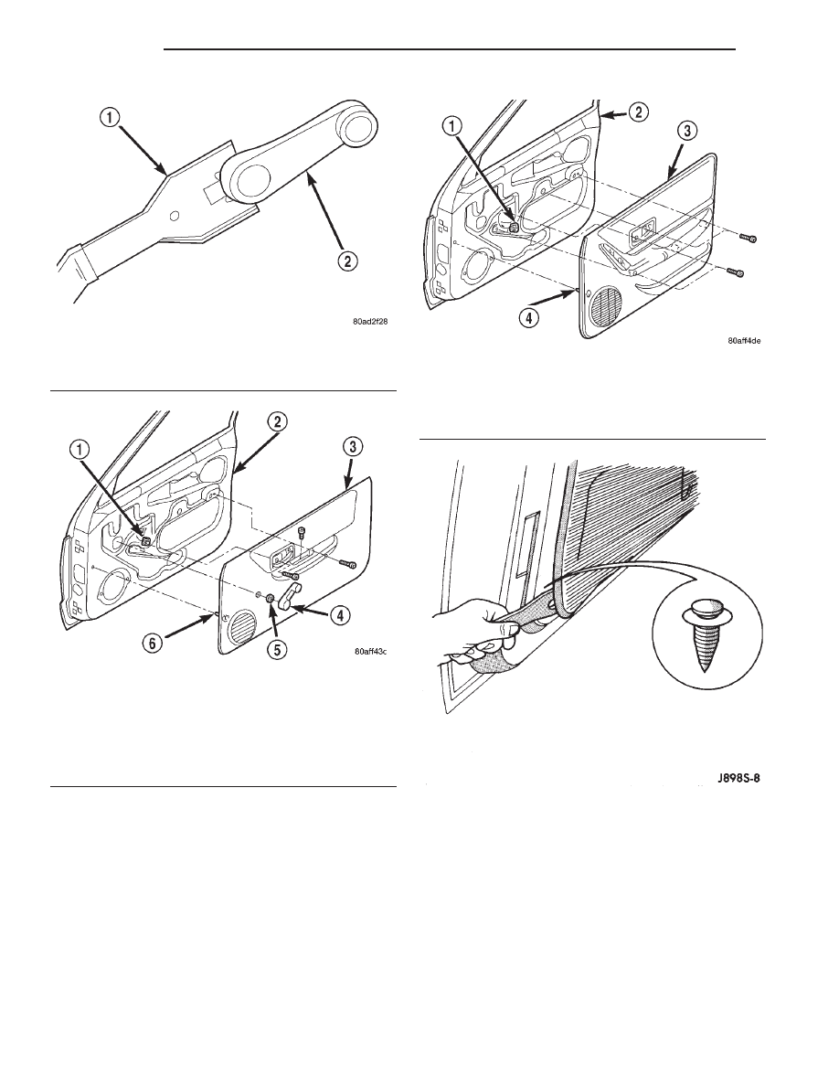
Fig. 21 Window Crank—Typical

1 – WINDOW CRANK REMOVAL TOOL
2 – WINDOW CRANK

Fig. 22 Front Door Trim Panel-Manual Window

1 – U-NUT
2 – DOOR
3 – TRIM PANEL
4 – WINDOW CRANK
5 – SPACER
6 – PUSH-IN FASTENER

Fig. 23 Front Door Trim Panel-Power Window

1 – U-NUT
2 – DOOR
3 – TRIM PANEL
4 – PUSH-IN FASTENER

Fig. 24 Detaching Trim Panel Push-In Fasteners

23 - 34

BODY

XJ

REMOVAL AND INSTALLATION (Continued)

(4) Engage clips attaching wire harnesses to the

door inner panel.

(5) Install door trim panel.

FRONT DOOR

REMOVAL

(1) Remove door restraint (check) retaining pin.
(2) For vehicles equipped with power windows,

power mirrors and power door locks, remove trim
panel and waterdam. Disconnect all components and
route wire harness out of door.

(3) Remove bolts that attach hinge to door (Fig.

26).

(4) Remove door from vehicle.

INSTALLATION

(1) Position door in body opening.
(2) Align door hinges, plates and shims and install

bolts. Tighten bolts to 3 N·m (2 ft. lbs.) torque.

(3) Install door restraint (check) pin.
(4) If applicable, route and connect wire harness

connectors.

(5) Install door waterdam and trim panel.

FRONT DOOR HINGE

REMOVAL

(1) Remove door restraint (check) retaining pin.
(2) Remove door hinge bolts and shims (Fig. 26).
(3) Retain door hinge shims for correct installa-

tion.

INSTALLATION

(1) Position hinge plates and shims on door face.

(2) Align door hinges and shims with bolt holes

and install hinge bolts. Tighten bolts to 3 N·m (2 ft.
lbs.) torque.

(3) Adjust/align latch striker and latch as neces-

sary.

(4) Install door restraint (check) retaining pin.

FRONT DOOR RESTRAINT

REMOVAL

(1) Remove door trim panel.
(2) Remove door radio speaker from door inner

panel.

(3) Remove door restraint (check) retaining pin

from bracket with a punch.

(4) Remove nuts and remove restraint via speaker

opening. (Fig. 27).

INSTALLATION

(1) Position door restraint in door by way of open-

ing and install nuts.

NOTE: Ensure the spring on the door restraint is
facing outward.

(2) Position door restraint in bracket with holes

aligned and insert retaining pin.

(3) Install radio speaker and door trim panel.

FRONT DOOR OUTSIDE HANDLE

REMOVAL

(1) Remove the door trim panel and waterdam.

Fig. 25 Push-In Fasteners

1 – LOCATING PINS
2 – TRIM PANEL
3 – PUSH-IN FASTENERS

Fig. 26 Front Door Hinge

1 – UPPER HINGE
2 – SHIM
3 – LOWER HINGE
4 – FRONT DOOR

XJ

BODY

23 - 35

REMOVAL AND INSTALLATION (Continued)

(2) Remove the access hole cover and remove the

rearward nut attaching the door handle to the door.
(Fig. 28).

(3) Disconnect the handle-to-latch rod from the

handle latch release lever arm.

(4) Remove the forward nut attaching the handle

to the door.

(5) Separate the handle from the door.

INSTALLATION

(1) Position the handle in the door.

(2) Install the forward nut attaching the handle to

the door.

(3) Connect the latch to handle rod, to the handle

latch release lever arm.

(4) Install the rearward nut attaching the door

handle to the door.

(5) Install the access hole cover.
(6) Install the door waterdam and trim panel.

FRONT DOOR LOCK CYLINDER

REMOVAL

(1) Remove the door trim panel.
(2) Peel back waterdam to access lock cylinder.
(3) Disconnect the door latch-to-lock cylinder rod

at the door latch (Fig. 29).

(4) Remove the lock cylinder retainer clip.
(5) Remove the lock cylinder.
(6) If applicable, remove the door latch-to-lock cyl-

inder rod from the original lock cylinder. Connect it
to the replacement lock cylinder.

INSTALLATION

(1) Position the lock cylinder and in the door open-

ing.

(2) Install the retainer clip.
(3) Connect the door latch-to-lock cylinder rod to

the door latch.

(4) Press the waterdam into position.
(5) Install the door trim panel.

Fig. 27 Door Restraint (Check)

1 – A-PILLAR
2 – RETAINING PIN
3 – NUT
4 – DOOR RESTRAINT
5 – RESTRAINT BRACKET
6 – DOOR INNER PANEL
7 – SPEAKER OPENING

Fig. 28 Front Door Outside Handle

1 – OUTSIDE DOOR HANDLE
2 – OUTSIDE HANDLE TO LATCH ROD
3 – DOOR LATCH
4 – OUTSIDE HANDLE TO LATCH ROD

Fig. 29 Door Lock Cylinder

1 – ACCESS PLUG
2 – RETAINER
3 – LOCK CYLINDER TO LATCH ROD
4 – LATCH
5 – LOCK CYLINDER TO LATCH ROD
6 – LOCK CYLINDER
7 – GASKET

23 - 36

BODY

XJ

REMOVAL AND INSTALLATION (Continued)

LOCK CYLINDERS

Ignition, door, deck lid, and rear hatch lock cylin-

ders are all codable to the key. Lock barrels, tum-
blers, and tumbler springs are available to allow the
technician to change replacement locks cylinders to
match the customer’s original key set. See the appro-
priate section in this manual for lock cylinder
removal. See the Mopar

t catalogue for part numbers

and lock coding procedures.

FRONT DOOR LATCH

REMOVAL

(1) Remove door trim panel and waterdam.
(2) Remove screws attaching latch to door.
(3) Disconnect all rods from latch (Fig. 30).
(4) Disconnect power lock motor wire connector, if

equipped.

(5) Remove latch from door face.

INSTALLATION

(1) Position latch on door face.
(2) Connect power lock motor wire connector, if

equipped.

(3) Connect all rods to latch.
(4) Install screws attaching latch to door. Tighten

screws to 11 N·m (8 ft. lbs.) torque.

(5) Install waterdam and door trim panel.

FRONT DOOR LATCH STRIKER

REMOVAL

(1) Using a grease pencil or equivalent, mark posi-

tion of striker.

(2) Remove screws attaching striker to B-pillar

(Fig. 31).

(3) Separate striker from B-pillar.

INSTALLATION

(1) Position and align striker on B-pillar.
(2) Install screws attaching striker to B-pillar.

Tighten screws to 28 N·m (20 ft. lbs.) torque.

FRONT DOOR INSIDE HANDLE ACTUATOR

REMOVAL

The front door inside handle actuator is heat

staked to the front door trim panel during the man-
ufacturing process.

(1) Remove the door trim panel.
(2) Using an X-ACTO knife or equivalent, cut the

melted tabs securing the inside handle to the door
trim panel.

(3) Separate the inside handle from the trim

panel.

INSTALLATION

(1) Position the inside handle in the trim panel.
(2) Heat stake the inside handle to the trim panel.
(3) Install the door trim panel.

FRONT DOOR INNER BELT WEATHERSTRIP

REMOVAL

(1) Roll window down.
(2) Remove door trim panel.
(3) Pull up on the rear corner of the weatherstrip

and lift from the door (Fig. 32).

Fig. 30 Door Latch

1 – FRONT DOOR LATCH
2 – LOCK BUTTON TO LATCH ROD
3 – INSIDE HANDLE TO LATCH ROD
4 – OUTSIDE HANDLE TO LATCH ROD
5 – LOCK CYLINDER TO LATCH ROD

Fig. 31 Front Door Latch Striker

1 – SPACER
2 – TAPPING PLATE
3 – STRIKER

XJ

BODY

23 - 37

REMOVAL AND INSTALLATION (Continued)


Content   ..  479  480  481  482   ..