Jeep XJ. Manual - part 480


  Index      Jeep     Jeep XJ - service repair manual 2001 year


Search            


Content   ..  478  479  480  481   ..


Jeep XJ. Manual - part 480


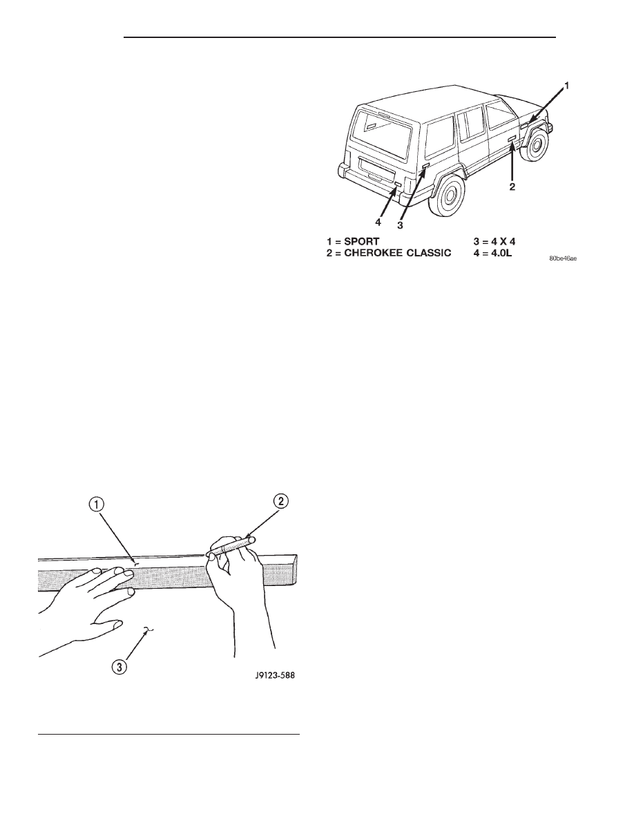
(6) Align a straight edge with the existing decal

ends (Fig. 13).

NOTE: If applicable, the body panel character line
can be used as the decal alignment reference.

(7) Position the decal and carrier on the body

panel (Fig. 14) and the mark length with a wax pen-
cil.

(8) Position the decal and carrier on the body

panel and hold it in-place with masking tape.

(9) Lift the bottom edge of decal and carrier. Use

the tape sections as hinges, and reverse the position
of decal and carrier.

CAUTION: Always remove the carrier from the
decal, never remove the decal from carrier

(10) Bend a corner of carrier outward and then,

with a flick of the finger, separate the corner of car-
rier from the decal.

(11) Return the decal back to its original position.

If a solution is being used, position adhesive side of
the decal on panel. Apply the solution to the outside
of the decal.

(12) Hold the decal against the panel surface while

separating the carrier from the decal.

(13) If applicable, remove the cover from face of

decal.

(14) Using a squeegee smooth out the decal to

remove wrinkles and/or air bubbles.

(15) Inspect the decal with reflected light to find

any damage. Remove all the air and/or moisture bub-
bles.

EXTERIOR NAMEPLATES

REMOVAL

NOTE: Exterior nameplates are attached to body
panels with adhesive tape.

(1) Apply a length of masking tape on the body,

parallel to the top edge of the nameplate to use as a
guide, if necessary.

(2) If temperature is below 21°C (70°F) warm

emblem with a heat lamp or gun. Do not exceed 52°C
(120°F) when heating emblem.

(3) Insert a plastic trim stick or a hard wood

wedge behind the emblem to separate the adhesive
backing from the body.

(4) Clean adhesive residue from body with MOPAR

Super Clean solvent or equivalent.

INSTALLATION

(1) Remove protective cover from adhesive tape on

back of emblem.

(2) Position emblem properly on body (Fig. 15).
(3) Press emblem firmly to body with palm of

hand.

(4) If temperature is below 21°C (70°F) warm

emblem with a heat lamp or gun to assure adhesion.
Do not exceed 52°C (120°F) when heating emblem.

Fig. 13 Decal Alignment Reference Mark

1 – STRAIGHT EDGE
2 – GREASE PENCIL
3 – BODY PANEL

Fig. 14 Body Decals

23 - 30

BODY

XJ

REMOVAL AND INSTALLATION (Continued)

SIDE VIEW MIRROR

REMOVAL

(1) Remove the door trim panel.
(2) Remove the screw attaching the mirror trim

cover/speaker grille to the door inner panel.

(3) remove push-in fastener attaching trim cover

to door inner panel (use special tool C-4829).

(4) Disconnect the power mirror wire connector, if

equipped.

(5) Remove the screws attaching the mirror to the

door (Fig. 16).

(6) Separate the mirror from the door.

INSTALLATION

(1) Position the mirror on the door.
(2) Install the screws attaching the mirror to the

door.

(3) Connect the power mirror wire connector, if

equipped.

(4) Install new push-in fastener.
(5) Install the mirror trim cover/speaker grille.
(6) Install the door trim panel.

FRONT FENDER FLARE

REMOVAL

(1) Remove the screw attaching the lower part of

flare to the bottom of the fender.

(2) Remove the nuts attaching the fender flare

retainer to the wheelhouse splash shield (Fig. 17).

(3) Remove the liner from the fender.
(4) Remove the fasteners attaching the fender flare

and retainer to the fender.

(5) Separate the fender flare and retainer from the

fender.

INSTALLATION

(1) Position the fender flare and retainer on the

fender.

(2) Install the nuts attaching the fender flare and

retainer to the wheelhouse fender.

(3) Install the screw attaching the lower part of

flare to the bottom of the fender.

Fig. 15 Exterior Nameplates

1 – CHEROKEE
2 – LIMITED-SPORT-CLASSIC

Fig. 16 Side View Mirror

1 – SIDE VIEW MIRROR
2 – WIRE HARNESS
3 – SEAL
4 – GROMMET
5 – DOOR

Fig. 17 Fender Flare

1 – FENDER FLARE
2 – RETAINER
3 – FENDER
4 – LINER
5 – PUSH NUT
6 – RETAINER

XJ

BODY

23 - 31

REMOVAL AND INSTALLATION (Continued)

FRONT WHEELHOUSE LINER

REMOVAL

(1) Hoist vehicle.
(2) Remove tire.
(3) Remove the push-in fasteners attaching the

wheelhouse liner to the inner fender.

(4) Separate the wheelhouse liner from the fender

(Fig. 18).

INSTALLATION

(1) Position the wheelhouse liner in the fender.
(2) Install new push-in fasteners attaching the

wheelhouse liner to the inner fender.

(3) Install tire.
(4) Lower vehicle.

RIGHT FRONT FENDER

REMOVAL

(1) Raise and support the hood.
(2) Remove the grille opening panel (GOP).
(3) If equipped, remove the radio antenna mast,

and components from the fender.

(4) Remove the coolant recovery bottle.
(5) Raise and support the vehicle.
(6) Remove the right front wheel.
(7) Remove the front bumper end cap.
(8) Remove the wheelhouse liner.
(9) Remove the fender flare and retainers.
(10) Disconnect all wire harness connectors.
(11) Remove the air deflector.
(12) Remove the fender lower screws (Fig. 19).

(13) Remove the fender top, front and the rear

screws.

(14) Remove the screws attaching the fender to the

inner support bracket (Fig. 20).

(15) Separate the fender from the inner fender

panel.

INSTALLATION

(1) Position the fender on the inner fender panel.
(2) Install all fender screws finger-tight.
(3) Align the fender with the body panels and

tighten the screws attaching the fender to the body
panels.

(4) Install the air deflector.
(5) Install the fender flare and retainers.
(6) Install the wheelhouse liner.
(7) Install the front bumper end cap.
(8) Install the wheel, remove the support and

lower the vehicle.

(9) Install the grille opening panel (GOP).
(10) Install the radio antenna.

LEFT FRONT FENDER

REMOVAL

(1) Raise and support the hood.
(2) Remove the grille opening panel (GOP).
(3) Raise and support the vehicle.
(4) Remove the left front wheel.
(5) Remove the front bumper end cap.
(6) Remove the fender flare and retainers.
(7) Remove the wheelhouse liner.
(8) Remove the air deflector.
(9) Remove the fender lower screws.
(10) Remove the fender top, front and the rear

screws.

(11) Remove the screws attaching the fender to the

inner support bracket.

(12) Separate the fender from the inner fender

panel.

INSTALLATION

(1) Position the fender on the inner fender panel.
(2) Install all fender screws finger-tight.
(3) Align the fender with the body panels and

tighten the screws attaching the fender to the body
panels.

(4) Install the air deflector.
(5) Install the wheelhouse liner.
(6) Install the fender flare and retainers.
(7) Install the front bumper.
(8) Install the wheel, remove the support and

lower the vehicle.

(9) Install the grille opening panel (GOP).

Fig. 18 Front Wheelhouse Liner

1 – FENDER
2 – WHEELHOUSE LINER
3 – INNER FENDER PANEL
4 – BRACE
5 – PUSH-IN FASTENER
6 – RETAINER

23 - 32

BODY

XJ

REMOVAL AND INSTALLATION (Continued)

FRONT DOOR TRIM PANEL

REMOVAL

(1) Roll window down.
(2) Remove window crank, if equipped (Fig. 21).

(3) Remove the screws attaching the trim panel to

the door inner panel (Fig. 22) and (Fig. 23).

(4) Separate the trim panel fasteners from door

inner panel with a pry tool (use special tool C-4829)
(Fig. 24).

(5) Lift the trim panel up and outward to separate

from the inner belt seal.

(6) Move the door trim panel outward and discon-

nect the handle-to-latch rods.

(7) Disconnect the power door locks/windows/mir-

rors wire harness connectors, if equipped.

(8) Remove the trim panel from door.

INSTALLATION

(1) Replace any broken or damaged push-in fasten-

ers.

(2) Connect the power door locks/windows/mirrors

wire harness connectors, if equipped.

(3) Move the door trim panel outward and connect

the handle-to-latch rods.

(4) Position the trim panel on the inner belt seal

and push down to seat.

(5) Align the locating pins and push- (Fig. 25) in

fasteners. Press inward to secure.

(6) Install the screws attaching the trim panel to

the door inner panel.

(7) Install the window crank, if equipped.

Fig. 19 Right Front Fender

1 – SCREW
2 – HOOD BUMPER
3 – U-NUT
4 – INNER FENDER PANEL
5 – FENDER BRACE

6 – FRAME SILL-TO-BAFFLE BRACE
7 – U-NUT
8 – OUTER FENDER PANEL
9 – U-NUT

Fig. 20 Inner Support Bracket

1 – U-NUT
2 – FRONT FENDER
3 – SUPPORT BRACKET

XJ

BODY

23 - 33

REMOVAL AND INSTALLATION (Continued)


Content   ..  478  479  480  481   ..