Jeep XJ. Manual - part 458


  Index      Jeep     Jeep XJ - service repair manual 2001 year


Search            


Content   ..  456  457  458  459   ..


Jeep XJ. Manual - part 458


(4) Apply liberal quantity of petroleum jelly to new

rear seal and to output shaft. Petroleum jelly is
needed to protect seal lips during installation.

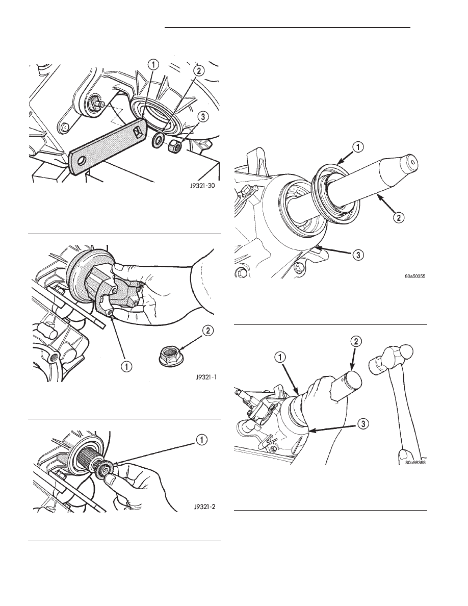
(5) Slide seal onto Seal Protector 6992 (Fig. 77).

Slide seal protector and seal onto output shaft.

(6) Slide Installer C-4076-B onto seal protector

with the recessed side of the tool toward the seal.
Drive seal into rear bearing retainer with Installer
C-4076-B and Handle MD-998323 (Fig. 78).

(7) Install rear slinger with Installer 8408.
(8) Install boot on output shaft slinger and crimp

retaining clamp with tool C-4975-A (Fig. 79).

Fig. 74 Range Lever Installation

1 – RANGE LEVER
2 – WASHER
3 – LOCKNUT

Fig. 75 Output Shaft Yoke Installation

1 – OUTPUT SHAFT YOKE
2 – YOKE NUT

Fig. 76 Yoke Seal Washer Installation

1 – YOKE SEAL WASHER

Fig. 77 Output Shaft Seal and Protector

1 – OUTPUT SHAFT SEAL
2 – SPECIAL TOOL 6992
3 – TRANSFER CASE

Fig. 78 Rear Seal Installation

1 – SPECIAL TOOL C-4076–B
2 – SPECIAL TOOL MD998323
3 – TRANSFER CASE

21 - 368

NV231 TRANSFER CASE

XJ

DISASSEMBLY AND ASSEMBLY (Continued)

CLEANING AND INSPECTION

NV231 TRANSFER CASE

Clean the transfer case parts with a standard

parts cleaning solvent. Remove all traces of sealer
from the cases and retainers with a scraper and 3M
all purpose cleaner. Use compressed air to remove
solvent residue from oil feed passages in the case
halves, retainers, gears, and shafts.

The oil pickup screen can be cleaned with solvent.

Shake excess solvent from the screen after cleaning
and allow it to air dry. Do not use compressed air.

MAINSHAFT/SPROCKET/HUB INSPECTION

Inspect the splines on the hub and shaft and the

teeth on the sprocket (Fig. 80). Minor nicks and
scratches can be smoothed with an oilstone. However,
replace any part that is damaged.

Check the contact surfaces in the sprocket bore

and on the mainshaft. Minor nicks and scratches can
be smoothed with 320–400 grit emery cloth but do
not try to salvage the shaft if nicks or wear is severe.

INPUT GEAR AND PLANETARY CARRIER

Check the teeth on the gear (Fig. 81). Minor nicks

can be dressed off with an oilstone but replace the
gear if any teeth are broken, cracked, or chipped. The
bearing surface on the gear can be smoothed with
300–400 grit emery cloth if necessary.

Examine the carrier body and pinion gears for

wear or damage. The carrier will have to be replaced
as an assembly if the body, pinion pins, or pinion
gears are damaged.

Check the lock ring and both thrust washers for

wear or cracks. Replace them if necessary. Also
replace the lock retaining ring if bent, distorted, or
broken.

Fig. 80 Mainshaft, Mode Hub, And Drive Sprocket

1 – MODE HUB
2 – DRIVE SPROCKET

3 – MAINSHAFT
4 – MODE HUB RETAINING RING

Fig. 79 Slinger Boot Installation

1 – SPECIAL TOOL C-4975–A
2 – SLINGER
3 – BOOT
4 – CLAMP

XJ

NV231 TRANSFER CASE

21 - 369

CLEANING AND INSPECTION (Continued)

SHIFT FORKS/HUBS/SLEEVES

Check condition of the shift forks and mode fork

shift rail (Fig. 82). Minor nicks on the shift rail can
be smoothed with 320–400 grit emery cloth.

Inspect the shift fork wear pads (Fig. 83). The

mode fork pads are serviceable and can be replaced if
necessary. The range fork pads are not serviceable.

The fork must be replaced as an assembly if the pads
are worn or damaged.

Check both of the sleeves for wear or damage,

especially on the interior teeth. Replace the sleeves if
wear or damage is evident.

REAR RETAINER/BEARING/ SEAL/SLINGER/BOOT

Inspect the retainer components (Fig. 84). Replace

the bearing if rough or noisy. Check the retainer for

Fig. 83 Shift Fork And Wear Pad Locations

1 – RANGE FORK
2 – MODE FORK
3 – WEAR PADS (SERVICEABLE)
4 – WEAR PADS (NON-SERVICEABLE)

Fig. 81 Input Gear And Carrier Components

1 – PLANETARY CARRIER
2 – REAR THRUST WASHER
3 – FRONT THRUST WASHER

4 – CARRIER LOCK RING
5 – CARRIER LOCK RETAINING RING
6 – INPUT GEAR

Fig. 82 Shift forks

1 – RANGE FORK
2 – MODE FORK AND RAIL
3 – MODE SPRING

21 - 370

NV231 TRANSFER CASE

XJ

CLEANING AND INSPECTION (Continued)

cracks or wear in the bearing bore. Clean the
retainer sealing surfaces with a scraper and 3M all
purpose cleaner. This will ensure proper adhesion of
the sealer during reassembly.

Replace the slinger and seal outright; do not reuse

either part.

Replace any part if distorted, bent, or broken. Also

replace the boot if cut or torn. Replace the boot band
clamps, do not reuse them.

REAR OUTPUT SHAFT/YOKE/DRIVE CHAIN

Check condition of the seal contact surfaces of the

yoke slinger (Fig. 85). This surface must be clean and
smooth to ensure proper seal life. Replace the yoke nut
and seal washer as neither part should be reused.

Inspect the shaft threads, sprocket teeth, and bear-

ing surfaces. Minor nicks on the teeth can be
smoothed with an oilstone. Use 320–400 grit emery
to smooth minor scratches on the shaft bearing sur-
faces. Rough threads on the shaft can be chased if
necessary. Replace the shaft if the threads are dam-
aged, bearing surfaces are scored, or if any sprocket
teeth are cracked or broken.

Examine the drive chain and shaft bearings.

Replace the chain and both sprockets if the chain is
stretched, distorted, or if any of the links bind.
Replace the bearings if rough, or noisy.

LOW RANGE ANNULUS GEAR

Inspect annulus gear condition carefully. The gear

is only serviced as part of the front case. If the gear
is damaged, it will be necessary to replace the gear
and front case as an assembly. Do not attempt to
remove the gear (Fig. 86)

FRONT-REAR CASES AND FRONT RETAINER

Inspect the cases and retainer for wear and dam-

age. Clean the sealing surfaces with a scraper and
3M all purpose cleaner. This will ensure proper
sealer adhesion at assembly. Replace the input
retainer seal; do not reuse it.

Check case condition. If leaks were a problem, look

for gouges and severe scoring of case sealing sur-
faces. Also make sure the front case mounting studs
are in good condition.

Fig. 84 Rear Retainer Components

1 – REAR RETAINER
2 – REAR BEARING I. D. RETAINING RING
3 – REAR SEAL
4 – BOOT

5 – BAND CLAMPS
6 – REAR SLINGER
7 – REAR BEARING O. D. RETAINING RING
8 – REAR BEARING

XJ

NV231 TRANSFER CASE

21 - 371

CLEANING AND INSPECTION (Continued)


Content   ..  456  457  458  459   ..