Jeep XJ. Manual - part 456


  Index      Jeep     Jeep XJ - service repair manual 2001 year


Search            


Content   ..  454  455  456  457   ..


Jeep XJ. Manual - part 456


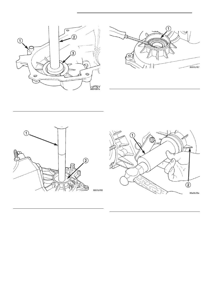
(4) Install front output shaft front bearing in case

with Tool Handle C-4171 and Installer 5064 (Fig. 43).

(5) Install output shaft front bearing retaining

ring (Fig. 44). Start ring into place by hand. Then
use small screwdriver to work ring into case groove.
Be sure ring is fully seated before proceeding.

(6) Install new front output seal in front case with

Installer Tool 8143 as follows:

(a) Place new seal on tool. Garter spring on

seal goes toward interior of case.

(b) Start seal in bore with light taps from ham-

mer (Fig. 45). Once seal is started, continue tap-
ping seal into bore until installer tool bottoms
against case.

(7) Remove the output shaft rear bearing with the

screw and jaws from Remover L-4454 and Cup 8148
(Fig. 46).

(8) Install new bearing with Tool Handle C-4171

and Installer 5066 (Fig. 47). The bearing bore is
chamfered at the top. Install the bearing so it is
flush with the lower edge of this chamfer (Fig. 48).

Fig. 42 Front Output Shaft Bearing Removal

1 – FRONT CASE
2 – SPECIAL TOOL C-4171
3 – SPECIAL TOOL 5065

Fig. 43 Front Output Shaft Bearing Installation

1 – SPECIAL TOOL C-4171
2 – SPECIAL TOOL 5064

Fig. 44 Installing Output Shaft Front Bearing

Retaining Ring

1 – WORK RETAINING RING INTO BORE GROOVE WITH SMALL

SCREWDRIVER

Fig. 45 Front Output Seal Installation

1 – INSTALLER 8143
2 – TRANSFER CASE

21 - 360

NV231 TRANSFER CASE

XJ

DISASSEMBLY AND ASSEMBLY (Continued)

(9) Using Remover C-4210 and Handle C-4171,

drive input shaft bearing from inside the annulus
gear opening in the case. (Fig. 49).

(10) Install locating ring on new bearing.
(11) Position case so forward end is facing upward.
(12) Using Remover C-4210 and Handle C-4171,

drive input shaft bearing into case. The bearing
locating ring must be fully seated against case sur-
face (Fig. 50).

(13) Remove input gear pilot bearing by inserting

a suitably sized drift into the splined end of the input
gear and driving the bearing out with the drift and a
hammer (Fig. 51).

(14) Install new pilot bearing with Installer 5065

and Handle C-4171 (Fig. 52).

Fig. 46 Output Shaft Rear Bearing Removal

1 – REAR CASE
2 – SPECIAL TOOL L-4454–1 AND L-4454–3
3 – SPECIAL TOOL 8148

Fig. 47 Output Shaft Rear Bearing Installation

1 – HANDLE C-4171
2 – OUTPUT SHAFT INNER BEARING
3 – INSTALLER 5066

Fig. 48 Output Shaft Rear Bearing Installation Depth

1 – BEARING (SEATED) AT LOWER EDGE OF CHAMFER
2 – CHAMFER

Fig. 49 Input Shaft Bearing Removal

1 – SPECIAL TOOL C-4171
2 – SPECIAL TOOL C-4210

XJ

NV231 TRANSFER CASE

21 - 361

DISASSEMBLY AND ASSEMBLY (Continued)

(15) Remove front bearing retainer seal with suit-

able pry tool.

(16) Install new front bearing retainer seal with

Installer 7884 (Fig. 53).

(17) Remove seal from oil pump housing with a

suitable pry tool

Fig. 50 Seating Input Shaft Bearing

1 – SNAP RING
2 – INPUT SHAFT BEARING

Fig. 51 Remove Input Gear Pilot Bearing

1 – DRIFT
2 – INPUT GEAR

Fig. 52 Install Input Gear Pilot Bearing

1 – SPECIAL TOOL C-4171
2 – SPECIAL TOOL 5065
3 – INPUT GEAR

Fig. 53 Install Front Bearing Retainer Seal

1 – FRONT BEARING RETAINER
2 – SPECIAL TOOL 7884

21 - 362

NV231 TRANSFER CASE

XJ

DISASSEMBLY AND ASSEMBLY (Continued)

(18) Install new seal in oil pump housing with

Installer 7888 (Fig. 54).

(19) Remove rear retainer bearing with Installer

8128 and Handle C-4171.

(20) Install rear bearing in retainer with Handle

C-4171 and Installer 5064 (Fig. 55).

INPUT AND LOW RANGE GEAR ASSEMBLY

(1) Lubricate gears and thrust washers (Fig. 56)

with recommended transmission fluid.

(2) Install first thrust washer in low range gear

(Fig. 56). Be sure washer tabs are properly aligned in
gear notches.

(3) Install input gear in low range gear. Be sure

input gear is fully seated.

(4) Install remaining thrust washer in low range

gear and on top of input gear. Be sure washer tabs
are properly aligned in gear notches.

(5) Install retainer on input gear and install snap-

ring.

INPUT GEAR AND LOW RANGE GEAR INSTALLATION

(1) Align and install low range/input gear assem-

bly in front case (Fig. 57). Be sure low range gear
pinions are engaged in annulus gear and that input
gear shaft is fully seated in front bearing.

(2) Install snap-ring to hold input/low range gear

into front bearing (Fig. 58).

(3) Clean gasket sealer residue from retainer and

inspect retainer for cracks or other damage.

(4) Apply a 3 mm (1/8 in.) bead of Mopar

t gasket

maker or silicone adhesive to sealing surface of
retainer.

(5) Align cavity in seal retainer with fluid return

hole in front of case.

CAUTION: Do not block fluid return cavity on seal-
ing surface of retainer when applying Mopar

T

gas-

ket maker or silicone adhesive sealer. Seal failure
and fluid leak can result.

(6) Install bolts to hold retainer to transfer case

(Fig. 59). Tighten to 21 N·m (16 ft. lbs.) of torque.

Fig. 54 Oil Pump Seal Installation

1 – HOUSING SEAL
2 – SPECIAL TOOL 7888
3 – OIL PUMP FEED HOUSING

Fig. 55 Installing Rear Bearing In Retainer

1 – SPECIAL TOOL C-4171
2 – SPECIAL TOOL 5064
3 – REAR RETAINER

Fig. 56 Input/Low Range Gear Components

1 – SNAP RING
2 – RETAINER PLATE
3 – INPUT GEAR
4 – LOW RANGE GEAR
5 – THRUST WASHERS

XJ

NV231 TRANSFER CASE

21 - 363

DISASSEMBLY AND ASSEMBLY (Continued)


Content   ..  454  455  456  457   ..