Jeep XJ. Manual - part 439


  Index      Jeep     Jeep XJ - service repair manual 2001 year


Search            


Content   ..  437  438  439  440   ..


Jeep XJ. Manual - part 439


• Outer diameter of bearing is 46.8 mm (1.844 in.)

and inside diameter is 26.0 mm (1.024 in.).

(68) Coat tabbed thrust race with petroleum jelly

and install it on planetary gear (Fig. 179). Race outer
diameter is 41.8 mm (1.646 in.) and inside diameter
is 27.1 mm (1.067 in.).

(69) Install assembled overdrive planetary gear

and clutch (Fig. 180).

(70) Coat thrust bearing and race assembly with

petroleum jelly and install it on clutch input shaft
(Fig. 181). Bearing and race outer diameter is 50.2
mm (1.976 in.) and inside diameter is 28.9 mm (1.138
in.).

(71) Coat thrust bearing race with petroleum jelly

and install it in oil pump (Fig. 182). Bearing race
outer diameter is 47.2 mm (1.858 in.) and inside
diameter is 28.1 mm (1.106 in.).

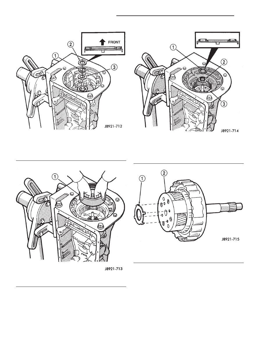
Fig. 176 Installing Overdrive Support Thrust Bearing

And Races

1 – THRUST BEARING
2 – UPPER RACE
3 – LOWER RACE

Fig. 177 Installing Overdrive Planetary Ring Gear

1 – OVERDRIVE PLANETARY RING GEAR

Fig. 178 Installing Ring Gear Thrust Bearing And

Race

1 – THRUST BEARING-RACE ASSEMBLY
2 – THRUST RACE (TABBED)
3 – OVERDRIVE PLANETARY RING GEAR

Fig. 179 Installing Planetary Thrust Race

1 – THRUST RACE (TABBED)
2 – OVERDRIVE PLANETARY

21 - 292

AW–4 AUTOMATIC TRANSMISSION

XJ

DISASSEMBLY AND ASSEMBLY (Continued)

(72) Lubricate and install replacement O–ring on

oil pump body.

(73) Install oil pump in case. Align pump and case

bolt holes and carefully ease pump into place.

CAUTION:

Do not use force to seat the pump. The

seal rings on the stator shaft could be damaged if
they bind or stick to the direct clutch drum.

(74) Tighten oil pump bolts to 22 N·m (16 ft. lbs.)

torque.

(75) Verify input shaft rotation. Shaft should

rotate smoothly and not bind.

(76) Lubricate and install new O–ring on trans-

mission throttle cable adapter and install cable in
case (Fig. 183).

Fig. 180 Installing Overdrive Planetary And Clutch

Assembly

1 – OVERDRIVE PLANETARY AND CLUTCH ASSEMBLY
2 – RING GEAR

Fig. 181 Installing Input Shaft Thrust Bearing And

Race Assembly

1 – THRUST BEARING AND RACE ASSEMBLY
2 – CLUTCH INPUT SHAFT

Fig. 182 Installing Oil Pump Thrust Race

1 – OIL PUMP
2 – PUMP THRUST RACE

Fig. 183 Installing Transmission Throttle Cable

1 – THROTTLE CABLE
2 – THROTTLE CAM

XJ

AW–4 AUTOMATIC TRANSMISSION

21 - 293

DISASSEMBLY AND ASSEMBLY (Continued)

(77) Check clutch and brake operation. Operate

clutches and brakes with compressed air applied
through feed holes in case (Fig. 184). Listen for
clutch and brake application. If you do not hear a
clutch or brake apply, disassemble transmission and
repair fault before proceeding. It is necessary to
block the overdrive clutch accumulator feed
hole No. 8 (Fig. 184) in order to check direct
clutch operation.

(78) Lubricate and install new O–rings on accumu-

lator pistons (Fig. 185).

(79) Assemble and install accumulator pistons and

springs (Fig. 185).

(80) Install new check ball body and spring (Fig.

186).

(81) Position valve body on case (Fig. 187).
(82) Install detent spring (Fig. 187).
(83) Align manual valve, detent spring and shift

sector (Fig. 187).

(84) Connect transmission throttle cable to throttle

valve cam (Fig. 188).

(85) Install and tighten valve body–to–case bolts to

10 N·m (7 ft. lbs.) torque.

(86) Connect valve body solenoid wires to solenoids

(Fig. 189).

(87) Install

new

O–ring

on

solenoid

harness

adapter and secure adapter to case.

(88) Install valve body oil tubes (Fig. 190). Tap

tubes into place with a plastic mallet. Be sure the

Fig. 184 Clutch And Brake Feed Hole Locations

Fig. 185 Accumulator Piston And Spring Installation

Fig. 186 Installing Check Ball Body And Spring

1 – CHECK BALL BODY AND SPRING

21 - 294

AW–4 AUTOMATIC TRANSMISSION

XJ

DISASSEMBLY AND ASSEMBLY (Continued)

flanged tube ends and straight tube ends are
installed as shown.

(89) Install new gaskets on oil screen and install

screen on valve body. Tighten screen bolts to 10 N·m
(7 ft. lbs.) torque.

(90) Install magnet in oil pan. Be sure magnet

does not interfere with valve body oil tubes.

(91) Apply Threebond

t Liquid Gasket TB1281,

P/N 83504038, to sealing surface of oil pan. Sealer
bead should be at least 3 mm (1/8 in.) wide. Install
pan on case and tighten pan bolts to 7 N·m (65 in.
lbs.) torque.

(92) Install transmission speed sensor rotor and

key on output shaft (Fig. 191).

(93) Install spacer and speedometer drive gear on

output shaft. Then install retaining snap ring (Fig.
192).

(94) Apply bead of Threebond

t Liquid Gasket

TB1281, P/N 83504038, to sealing surface at rear of
case (Fig. 193).

Fig. 187 Aligning Manual Valve, Shift Sector And

Detent Spring

1 – DETENT SPRING
2 – SHIFT SECTOR
3 – VALVE BODY
4 – MANUAL VALVE

Fig. 188 Connecting Transmission Throttle Cable

1 – THROTTLE CABLE
2 – THROTTLE CAM

Fig. 189 Connecting Valve Body Solenoid Wires

1 – SOLENOID WIRE CONNECTORS

Fig. 190 Installing Valve Body Oil Tubes

XJ

AW–4 AUTOMATIC TRANSMISSION

21 - 295

DISASSEMBLY AND ASSEMBLY (Continued)


Content   ..  437  438  439  440   ..